Tibial tray for total knee arthroplasty

a technology for arthroplasty and tibia, which is applied in the field of improved tibial trays, can solve the problems of increased difficulty, increased cost of modular devices, and difficulty, and achieve the effects of enhancing the ease with which excess cement may be removed, ensuring stability, and providing strength and rotational stability

Inactive Publication Date: 2009-04-28
HAIDUKEWYCH GEORGE J
View PDF21 Cites 34 Cited by
  • Summary
  • Abstract
  • Description
  • Claims
  • Application Information

AI Technical Summary

Benefits of technology

[0009]The present invention relates to an improved tibial tray used for total knee arthroplasty wherein the improved tray comprises a base plate having a top surface and a bottom surface, and an asymmetric keel depending from the bottom surface and, in a preferred construction, a pair of opposed fins depending from the bottom surface and integral with opposed sides of the keel. The asymmetric configuration of the keel not only permits insertion through a smaller incision, but also tends to expel cement toward the surgeon as the tray is inserted in place, enhancing the ease with which excess cement may be removed. The fins provide strength and rotational stability to the tray once it has been placed.

Problems solved by technology

One of the major technical hurdles in performing an accurate, minimally invasive total knee arthroplasty is obtaining adequate exposure in order to seat the currently available components, particularly the state-of-the-art tibial trays.
Even when traditional large incisions are used, the procedure is challenging.
With the advent of minimally invasive techniques, another level of difficulty is added because the components must be placed through smaller incisions in the patient's skin.
However, a relatively larger incision is still necessary for insertion of the keel or stem, and modular devices are frequently more expensive than unitary devices, and the parts may not mate properly.
Furthermore, intraoperative assembly is necessary, and this may prove to be more difficult when working through small incisions.
Finally, modularity can result in modular interface fatigue fracture, fretting, and / or debris generation that can compromise the effective life of the arthroplasty.

Method used


Image

  • Tibial tray for total knee arthroplasty
  • Tibial tray for total knee arthroplasty
  • Tibial tray for total knee arthroplasty

Examples


first embodiment

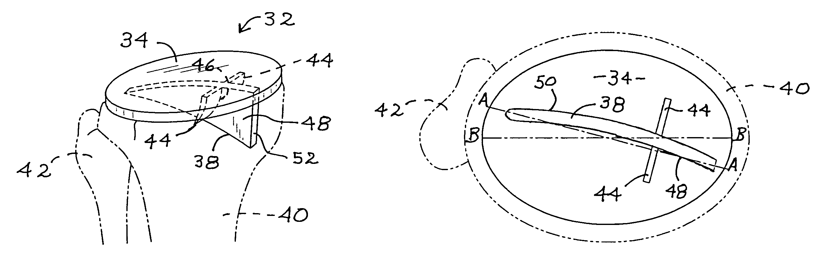
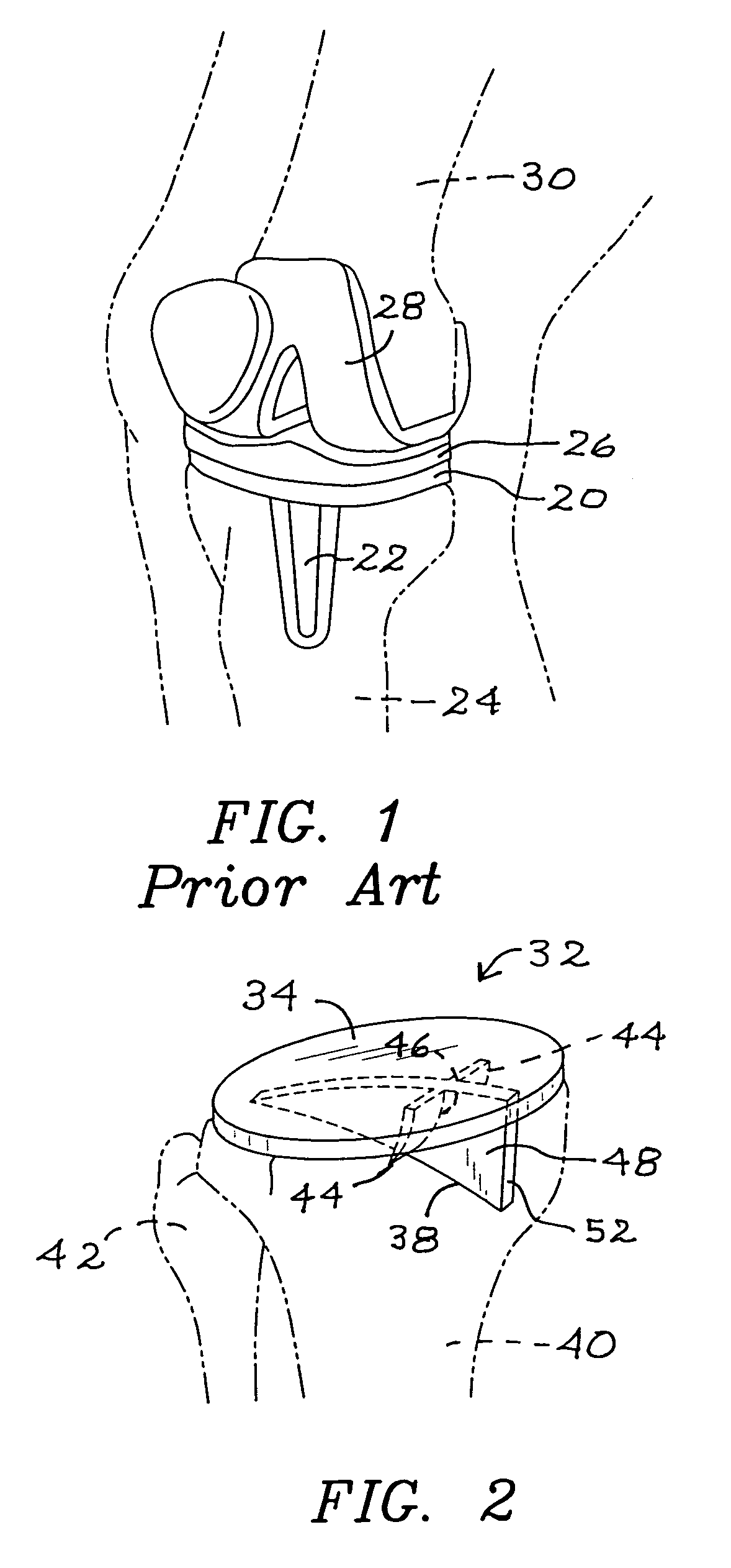
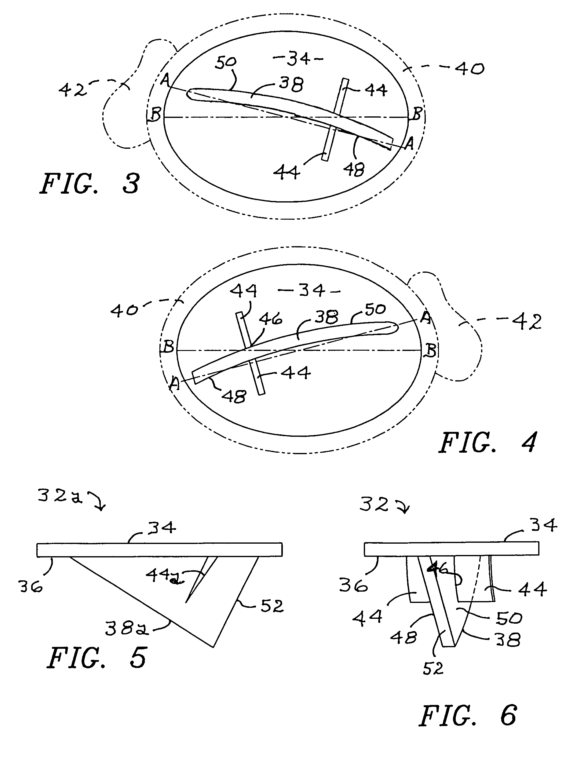
[0026]Embodiments of the improved tibial tray of this invention are shown in the remaining figures, and attention is first invited to the view of FIG. 2 wherein the improved tibial tray is generally indicated as 32. Tibial tray 32 includes a top surface 34 and a bottom surface 36. Integrally formed on bottom surface 36 and extending downwardly therefrom is asymmetric keel 38. Shown in phantom in the view of FIG. 2 is an anterior view of the patient's tibia 40 and fibula 42. Also shown in the view of FIG. 2 are a pair of opposed fins 44. Fins 44 are integrally formed on bottom surface 36 and extend downwardly, each including a keel edge 46 that is integral with a corresponding first side 48 and second side 50 of asymmetric keel 38. The view of FIG. 3 is a superior plan illustration of placement of tibial tray 32, as shown in the view of FIG. 2. The view of FIG. 4 illustrates placement of the improved tibial tray on the patient's other leg.

[0027]As can be seen in the views of FIGS. 2-...

second embodiment

[0030]The view of FIG. 5 depicts a second embodiment for the improved tibial tray of this invention, generally indicated as 32a. In this embodiment for tibial tray 32a, fins 44a are not curved, and asymmetric keel 38a is not curved. Furthermore, the embodiment for tibial tray 32a may include a single fin 44a, and the use of a single fin may be employed in all embodiments of this invention.

third embodiment

[0031]Turning to the view of FIG. 8, a third embodiment for the improved tibial tray is generally indicated as 32b. As can be clearly seen in the view of FIG. 8, asymmetric keel 38b is of a curved configuration, rather than angular. Of course, asymmetric keel 38b still includes an edge 52b that extends downwardly from bottom surface 36 to a maximum depth within tibia 40. In this embodiment of improved tibial tray 32b, asymmetric keel 38b is preferably curved as is keel 38, but may be straight as described with regard to keel 38a.

[0032]The view of FIG. 7 is provided to illustrate preparation of tibia 40 for insertion and attachment of the improved tibial tray of this invention. A trial tray 54 is attached to tibia 40 as by pins 56, then a chisel 58 is repeatedly struck by mallet 60 to form a void 62 for receiving the asymmetric keel of the improved tibial tray. It is, of course, to be understood that chisel 58 would be dimensioned and configured to provide a void 62 corresponding to...


PUM


Abstract

An improved one piece tibial tray uniquely characterized by its construction including an asymmetric keel extending from the bottom of the tibial tray base plate, whereby insertion of the tray during arthroplasty may be accomplished with a smaller than normal incision, enhancing the efficacy and safety of the surgical procedure. A fin on either or both sides of the asymmetric fin may be provided for enhanced stability of the tray.

Description

BACKGROUND OF THE INVENTION[0001]1. Field of the Invention[0002]The present invention relates to an improved tibial tray that is positioned on the patient's tibia for joint replacement in a total knee arthroplasty. The improved tibial tray of this invention is of a unitary construction and comprises a unique, asymmetric keel that permits insertion through a relatively smaller incision.[0003]2. Description of the Prior Art[0004]Total knee arthroplasty is a common procedure performed worldwide. This procedure traditionally requires wide exposure of the distal femur and proximal tibia in order to permit appropriate preparation of the bone surfaces for implanting the components. Most implants performed today in the United States are cemented in place with polymethylmethacrylate cement. Extraneous cement is traditionally cleaned, requiring additional exposure of the femur and tibia to ensure sufficient removal and to prevent potential third body debris.[0005]Over the past several years t...

Claims


Application Information

Patent Timeline
Patent Type & Authority Patents(United States)
IPC IPC(8): A61F2/38
CPCA61B17/1675A61B17/1764A61F2/389A61B17/1604
Inventor HAIDUKEWYCH, GEORGE J.
Owner HAIDUKEWYCH GEORGE J
Why Eureka
Try Eureka