Time-balanced multiplexer switching methods and apparatus

a multiplexer and switching method technology, applied in logic circuits, electric pulse generators, pulse generation by gas-filled tubes, etc., can solve problems such as substantial equal delay before the corresponding output signal, and achieve time-balanced multiplexer switching

Active Publication Date: 2009-04-28
MARVELL ISRAEL MISL
View PDF11 Cites 20 Cited by
  • Summary
  • Abstract
  • Description
  • Claims
  • Application Information

AI Technical Summary

Benefits of technology

[0008]The invention therefore advantageously allows time-balanced multiplexer switching with respect to selector input transitions. Furthermore, this time-balanced switching is achieved with minimal changes to existing multiplexer implementations.

Problems solved by technology

As a result, all selector input transitions preferably result in a substantially equal delay before the corresponding output signal transitions.

Method used


Image

  • Time-balanced multiplexer switching methods and apparatus
  • Time-balanced multiplexer switching methods and apparatus
  • Time-balanced multiplexer switching methods and apparatus

Examples


Embodiment Construction

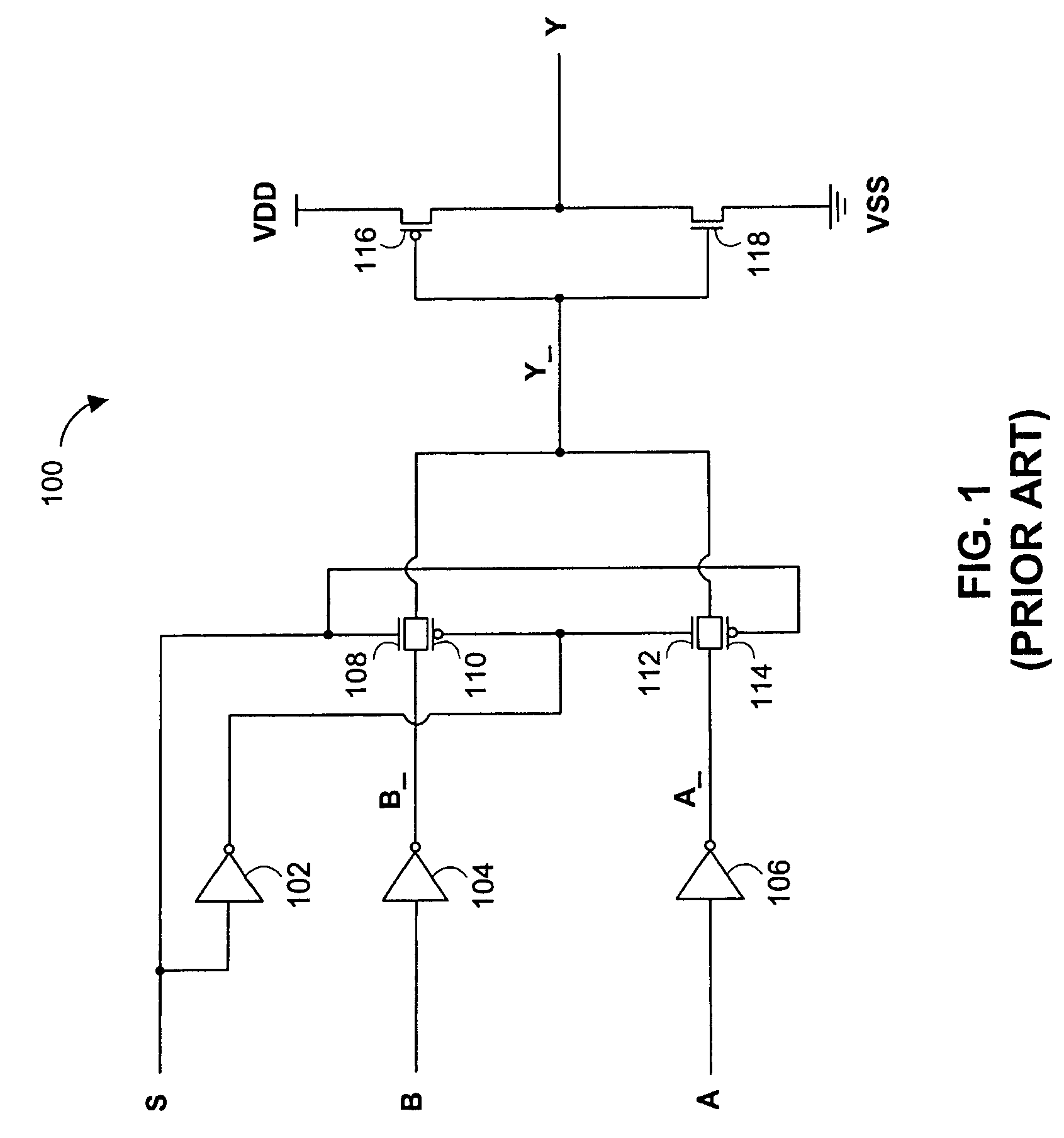
[0021]FIG. 1 is a circuit diagram of an illustrative multiplexer 100 that exhibits unbalanced switching. Selector input S selects between data inputs B and A. The selected data input is passed to data output Y through two stages of inversion. Voltage references are provided by the power source (“VDD”) and ground (“VSS”).

[0022]Selector input S is coupled to the gates of N-type metal-oxide semiconductor (“NMOS”) transistor 108 and P-type metal-oxide semiconductor (“PMOS”) transistor 114. Selector input S is also coupled to inverter 102, whose output is coupled to the gates of PMOS transistor 110 and NMOS transistor 112. Thus, transistors 108, 110, 112, and 114 serve as pass-gates that are operated by selector input S and an inversion of selector input S.

[0023]When the voltage of selector input S reflects a logical 0, transistors 112 and 114 will be activated, while transistors 108 and 110 will be deactivated. Accordingly, the logical value carried by data input A will be inverted by i...


PUM


Abstract

Methods and apparatus are provided for time-balanced switching of multiplexer circuits. An embodiment of the invention includes a transistor chain coupled to the output of the multiplexer circuit. The transistor chain preferably delays transitions that would otherwise occur relatively quickly, to match the timing of transitions that occur relatively slowly. The timing of relatively slow transitions is left unaltered. The invention advantageously allows all selector input transitions to yield a data output transition with a substantially constant delay.

Description

[0001]This application claims the benefit of provisional application No. 60 / 611,820, filed Sep. 20, 2004, which is hereby incorporated by reference herein in its entirety.BACKGROUND OF THE INVENTION[0002]This application relates to multiplexer circuits. More particularly, this application relates to time-balanced switching of multiplexer circuits.[0003]Multiplexers are well-known circuits that accept N selector inputs and 2N data inputs, and generate a single data output. Each binary combination of the N selector inputs will select a corresponding data input and transmit its value to the data output. In general, each data input and data output can be a bus of M bits. For simplicity of illustration, the discussion herein will focus on a multiplexer with a single selector input, two single-bit data inputs, and one single-bit data output. However, it will be understood that the concepts discussed herein could easily be generalized to accommodate N selector inputs and 2N data inputs, wh...

Claims


Application Information

Patent Timeline
Patent Type & Authority Patents(United States)
IPC IPC(8): H03K19/173G06F7/38H03K3/37
CPCH03K19/00323H03K17/005
Inventor ROSEN, EITANLIEBERMAN, DAN
Owner MARVELL ISRAEL MISL
Why Eureka
Try Eureka