Electromagnetic railgun projectile

a technology of electromagnetic railgun and projectile, which is applied in the direction of white arms/cold weapons, launching weapons, transportation and packaging, etc., can solve the problems of reducing the life of railguns, insufficient lethality mass delivered to the target, and in-bore lateral loads to the ilp, so as to increase the lift-to-drag ratio of electromagnetic railgun projectil

Inactive Publication Date: 2009-05-05
THE BOEING CO
View PDF15 Cites 17 Cited by
  • Summary
  • Abstract
  • Description
  • Claims
  • Application Information

AI Technical Summary

Benefits of technology

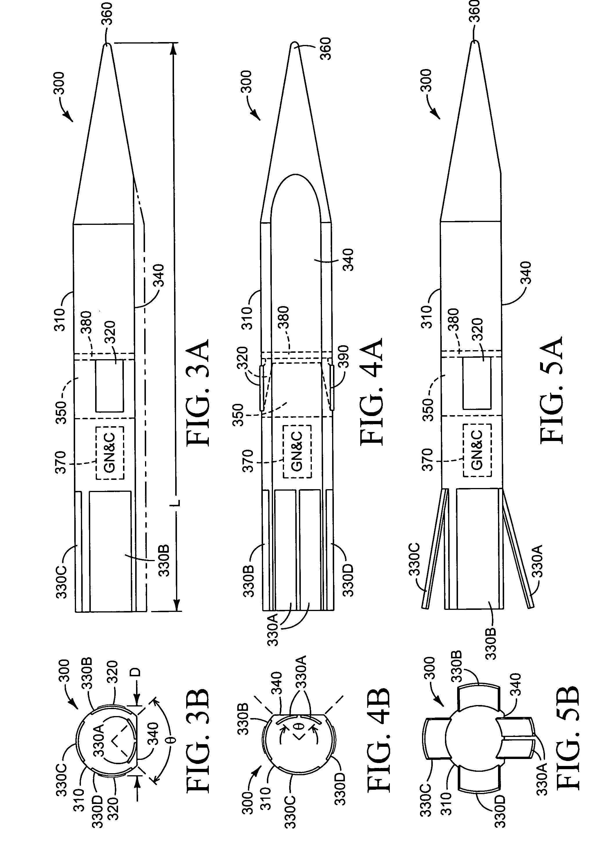
[0007]In another embodiment, an electromagnetic railgun projectile comprises a non-axisymmetric aeroshell having a substantially flat aerodynamic lifting surface extending along the length thereof. The lifting surface is configured to increase the lift-to-drag ratio of the electromagnetic railgun projectile during reentry.

Problems solved by technology

However, these components are traditionally only used during the launch process and are immediately discarded after bore disengagement.
Accordingly, one drawback associated with electromagnetic railguns is that insufficient lethality mass is delivered to the target when compared with conventional powder guns and tactical missiles.
In addition, for launch velocities greater than about 2.2 km / s, the armature can transition, thereby inducing undesirable in-bore lateral loads to the ILP and reducing rail life.
However, this approach results in a reduced engagement range for the electromagnetic railgun.

Method used


Image

  • Electromagnetic railgun projectile
  • Electromagnetic railgun projectile
  • Electromagnetic railgun projectile

Examples


Embodiment Construction

[0019]In the following detailed description, reference is made to the accompanying drawings that form a part hereof, and in which is shown by way of illustration specific illustrative embodiments in which the invention may be practiced. These embodiments are described in sufficient detail to enable those skilled in the art to practice the invention, and it is to be understood that other embodiments may be utilized and that various changes may be made without departing from the spirit and scope of the present invention. The following detailed description is, therefore, not to be taken in a limiting sense.

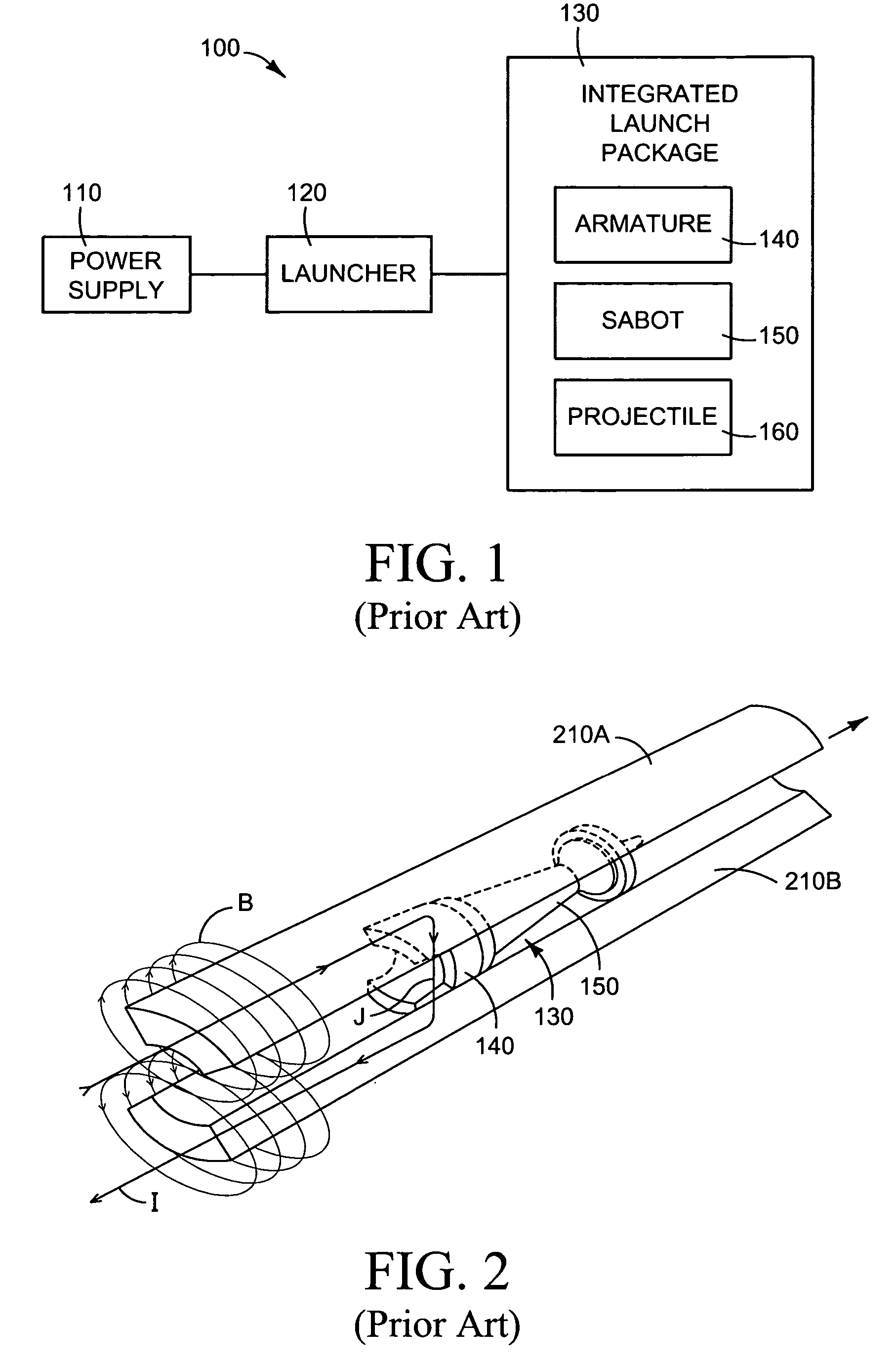
[0020]FIG. 1 is a block diagram of a conventional electromagnetic railgun system 100. In the illustrated embodiment, the system 100 comprises a power supply 110 coupled to a launcher 120, which cooperates with a conventional integrated launch package (ILP) 130, as described below. In some embodiments, the power supply 110 comprises a pulsed power supply with a pulse energy ranging fr...


PUM


Abstract

An electromagnetic railgun projectile is disclosed which includes an aeroshell having a substantially flat surface extending along the length thereof. The substantially flat surface is configured to increase the lift-to-drag ratio of the projectile during reentry. The projectile also includes an armature integrated into the aeroshell substantially near the center-of-gravity of the projectile, and a plurality of extendable flaps attached to the aeroshell. The flaps are capable of stabilizing the projectile during an unguided portion of its flight and maneuvering the projectile during a guided portion of its flight.

Description

BACKGROUND[0001]The present application is directed to electromagnetic railguns, and more particularly to projectiles launched from electromagnetic railguns.[0002]Electromagnetic railguns utilize an electromagnetic force called the Lorentz force to propel an electrically conductive integrated launch package (ILP). In a typical electromagnetic railgun, the ILP slides between two parallel rails and acts as a sliding switch or electrical short between the rails. By passing a large electrical current down one rail, through the ILP, and back along the other rail, a large magnetic field is built up behind the ILP, accelerating it to a high velocity by the force of the current times the magnetic field. An electromagnetic railgun is capable of launching an ILP to velocities greater than fielded powder guns, thereby achieving greater ranges and shorter flight times to engagement.[0003]An ILP typically includes three subsystems: (1) the armature; (2) the sabot; and (3) the projectile. The arm...

Claims


Application Information

Patent Timeline
Patent Type & Authority Patents(United States)
IPC IPC(8): F41F1/00
CPCF41B6/006F42B6/006
Inventor ELDER, DOUGLAS J.
Owner THE BOEING CO
Why Eureka
Try Eureka