Ink-jet having an arrangement to suppress variations in ink ejection

a technology of inkjet and arrangement, which is applied in the field of inkjet head, to achieve the effect of suppressing the variation of ink ejection characteristics

Active Publication Date: 2009-05-05
BROTHER KOGYO KK
View PDF31 Cites 2 Cited by
  • Summary
  • Abstract
  • Description
  • Claims
  • Application Information

AI Technical Summary

Benefits of technology

[0007]An object of the present invention is to provide an ink-jet head capable of suppressing a variation in ink ejection characteristics, and also to provide a method for manufacturing the ink-jet head.

Problems solved by technology

Such a construction may involve a problem that, among nozzles communicating with the respective pressure chambers in a pressure chamber group consisting of a plurality of adjacently-arranged pressure chambers, the nozzles that communicate with pressure chambers located outermost with respect to an arrangement direction of the plurality of pressure chambers and the nozzles that communicate with the other pressure chambers located inside exhibit different ink ejection characteristics from each other.

Method used


Image

  • Ink-jet having an arrangement to suppress variations in ink ejection
  • Ink-jet having an arrangement to suppress variations in ink ejection
  • Ink-jet having an arrangement to suppress variations in ink ejection

Examples


Embodiment Construction

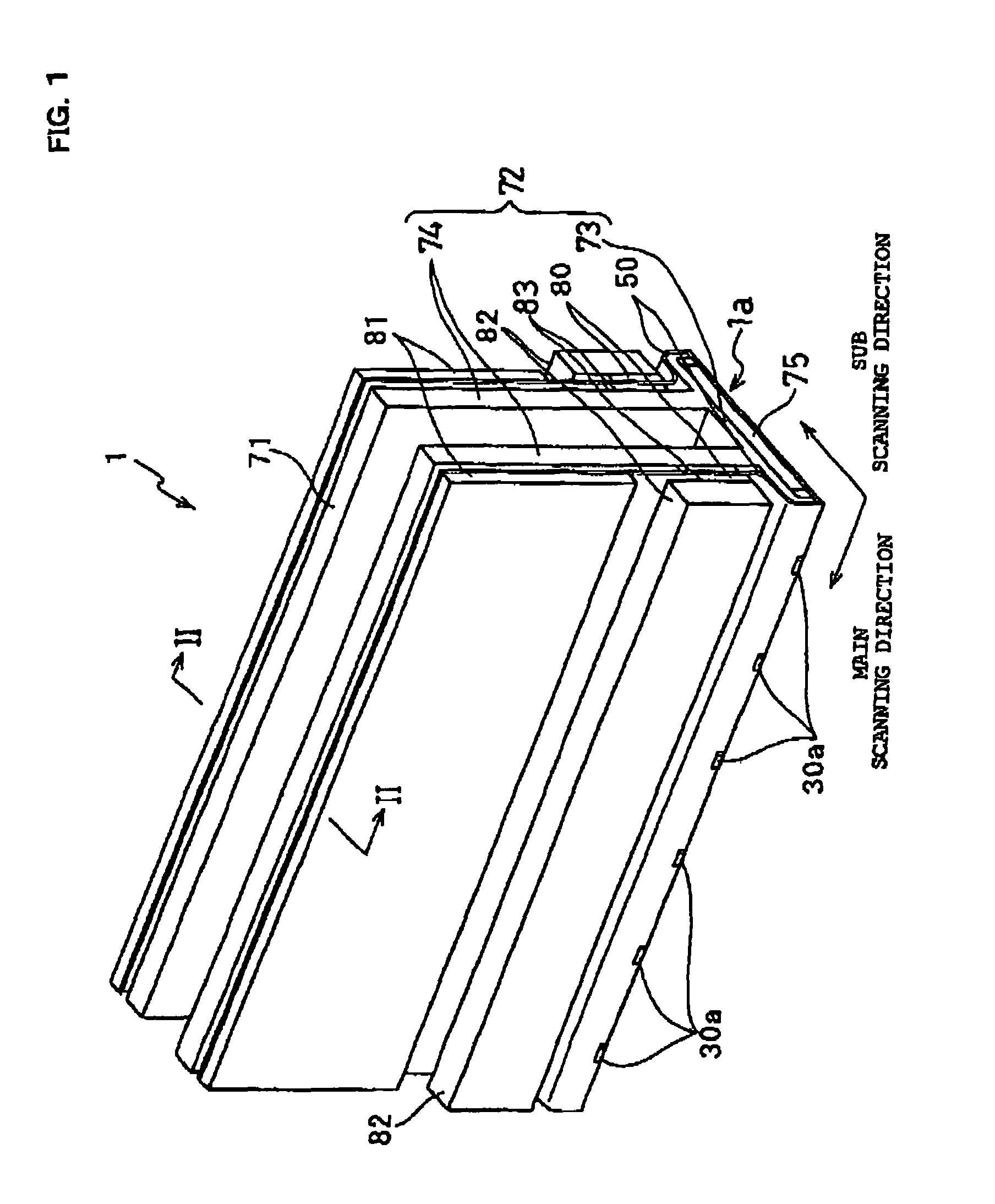
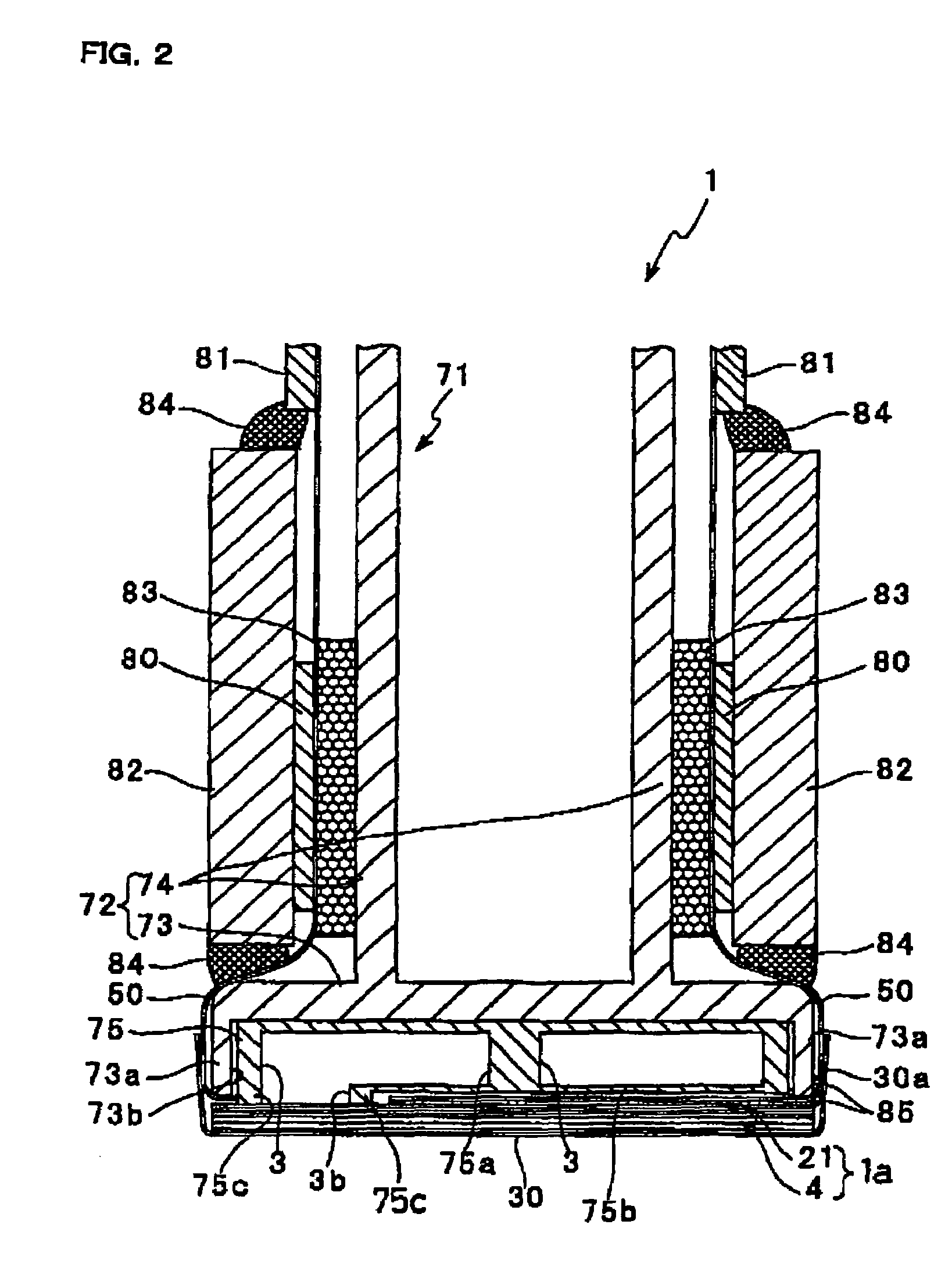
[0032]A general structure of an ink-jet head according to an embodiment of the present invention will firstly be described with reference to FIGS. 1, 2, and 3.

[0033]An ink-jet head 1 is used in an ink-jet printer of line-printing type. As illustrated in FIGS. 1 and 2, the ink-jet head 1 has a head main body 1a and a base 71 that supports the head main body 1a. The head main body 1a has, in a plan view, a rectangular shape extending in one direction of a main scanning direction. The base 71 comprises a base block 75 partially bonded to the head main body 1a, and a holder 72 bonded to an upper face of the base block 75 for supporting the base block 75.

[0034]The base block 75, made of a metal material such as stainless steel, is a substantially rectangular parallelepiped member having substantially the same length as a longitudinal length of the head main body 1a. The base block 75 functions as a light-weight structure for reinforcing the holder 72. The holder 72 is made up of a holder...


PUM


Abstract

A head main body includes a passage unit in which pressure chambers are arranged adjacent to each other along its surface, and an actuator unit that is fixed to the passage unit to change the volume of the pressure chambers. A piezoelectric sheet constituting a piezoelectric element in the actuator unit spans a plurality of pressure chambers. On a surface of the piezoelectric sheet, formed are not only individual electrodes corresponding to respective pressure chambers but also dummy electrodes. Any individual electrode is surrounded with other individual electrodes or the dummy electrodes arranged in substantially the same pattern. Both the individual electrodes and the dummy electrodes are formed by arranging conductive pastes at predetermined positions on the piezoelectric sheet and then sintering these pastes.

Description

BACKGROUND OF THE INVENTION[0001]1. Field of the Invention[0002]The present invention relates to an ink-jet head that ejects ink onto a recording medium to conduct recordings, and also to a method for manufacturing the ink-jet head.[0003]2. Description of Related Art[0004]In some ink-jet heads used in ink-jet recording apparatuses such as ink-jet printers, three linear pressure chambers are arranged on a surface of a passage unit having ink passage as formed therein such that the three linear pressure chambers are adjacent to each other with respect to a perpendicular direction to their linear direction, and, in addition, a piezoelectric actuator spanning the three pressure chambers is arranged on the surface of the passage unit on which the pressure chambers are formed (see U.S. Pat. No. 5,402,159). The piezoelectric actuator has a plurality of piezoelectric sheets constituting a piezoelectric element. A common electrode shared by all the pressure chambers and three individual elec...

Claims


Application Information

Patent Timeline
Patent Type & Authority Patents(United States)
IPC IPC(8): B41J2/45B41J2/145B41J2/045B41J2/055B41J2/14B41J2/16
CPCB41J2/14209B41J2/1609B41J2/1623B41J2/1632B41J2002/14217B41J2002/14225B41J2002/14306B41J2002/14459B41J2002/14491B41J2202/20
Inventor HIROTA, ATSUSHI
Owner BROTHER KOGYO KK
Why Eureka
Try Eureka