Thermally sprayed conformal seal

a conformal seal and thermal spray technology, applied in the direction of machines/engines, liquid fuel engines, lighting and heating apparatus, etc., can solve the problems of thermal expansion of individual components and possible gap formation between components

Inactive Publication Date: 2009-05-05
SIEMENS ENERGY INC
View PDF29 Cites 43 Cited by
  • Summary
  • Abstract
  • Description
  • Claims
  • Application Information

AI Technical Summary

Problems solved by technology

Gas turbine engines may have high turbine inlet temperatures, which cause thermal expansion of individual components.
Gaps may be formed between components that would allow for the undesirable passage of combustion gases or cooling airflow if the gap were not adequately sealed.

Method used


Image

  • Thermally sprayed conformal seal
  • Thermally sprayed conformal seal
  • Thermally sprayed conformal seal

Examples


Embodiment Construction

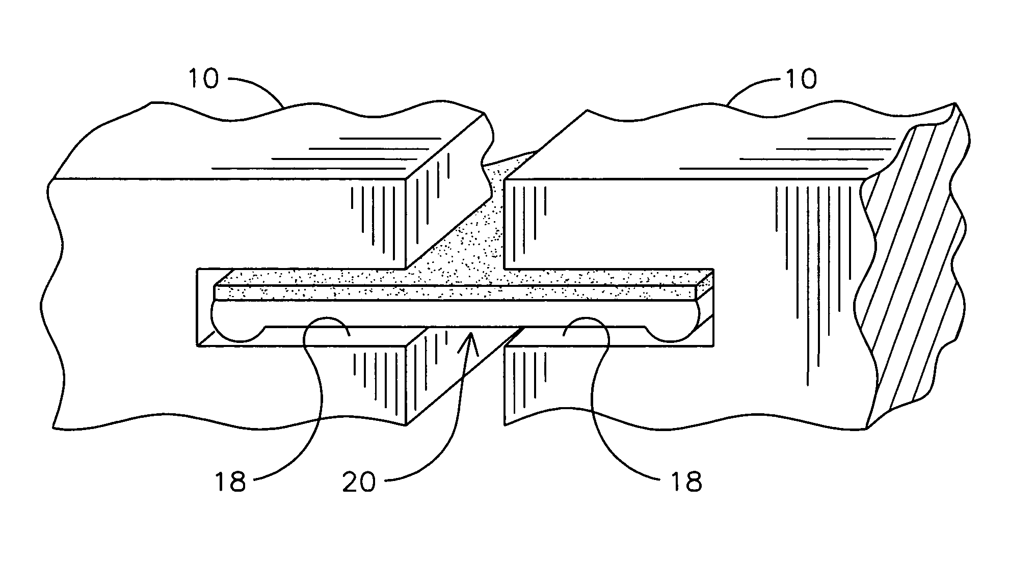
[0009]Interstage gas leakage between and around components is deleterious to combustion turbine engine performance, efficiency and emissions. Leakage reduction may be achieved by using various seals such as solid metal flat seals, riffle seals, and various spring seals, among others. The inventor has determined that certain types of these seals frequently suffer from a certain amount of “bridging”, which may result from adjacent components twisting during operation. If two adjacent components, such as vane segments of a combustion turbine engine, for example, between which the seal interfaces are twisted or not perfectly parallel the seal will tend to form a straight-line path between the components resulting in increased leakage through that path. Twisting has been observed in combustion engine components due to thermal deflection and off-axial aero loading.

[0010]Embodiments of the invention may be used in a wide range of operating environments including combustion turbine engines ...


PUM

PropertyMeasurementUnit
porosityaaaaaaaaaa
temperaturesaaaaaaaaaa
temperatureaaaaaaaaaa

Abstract

A conformal seal (20) for sealing air flow between a cooling airflow path and a hot gas flow path within a combustion turbine engine. The conformal seal (20) may be fitted within cooperating side slots of adjacent vane segments (10) within the combustion turbine engine. The conformal seal (20) may include an elongated metallic substrate (22, 40) forming an upper surface and a lower surface. A conformal coating (26, 44) may be deposited over one or both surfaces of the substrate (22, 40). The conformal coating (26, 44) may be deposited to a depth so that a point contact between the conformal coating (26, 44) and respective interior walls of the side slots wears the conformal coating (26, 44) to establish surface area contact there between. The surface area contact improves a sealing function between the conformal coating (26, 44) and the respective interior walls during operation of the combustion turbine engine.

Description

FIELD OF THE INVENTION[0001]This invention relates generally to combustion turbine engines and in particular to seals used within the gas flow path for inhibiting the leakage of combustion gases between or among components within the combustion turbine engine.BACKGROUND OF THE INVENTION[0002]Combustion turbine engines such as ones used for power generation define cooling air and combustion gas flow paths that need to be separated from one another for optimum operating efficiency. Gas turbine engines may have high turbine inlet temperatures, which cause thermal expansion of individual components. In such cases, adjacent components are sometimes spaced from one another to avoid high thermal stresses and the formation of cracks during operation. Gaps may be formed between components that would allow for the undesirable passage of combustion gases or cooling airflow if the gap were not adequately sealed.BRIEF DESCRIPTION OF THE DRAWINGS[0003]FIG. 1 is a perspective view of vane ring seg...

Claims


Application Information

Patent Timeline
Patent Type & Authority Patents(United States)
IPC IPC(8): F01D9/04
CPCF01D11/008F05D2230/90F05D2300/611F05D2240/11
Inventor ALLEN, DAVID B.
Owner SIEMENS ENERGY INC
Why Eureka
Try Eureka