Display device

a display device and display technology, applied in the field of optical switches, can solve the problems of reducing brightness for smaller pixels, moving or breaking the oil layer, and increasing the reflectivity of the image,

Active Publication Date: 2009-05-05
LIQUAVISTA BV
View PDF11 Cites 35 Cited by
  • Summary
  • Abstract
  • Description
  • Claims
  • Application Information

AI Technical Summary

Benefits of technology

[0016]By lowering the walls to 20 μm thickness, or less, the device can be operating in a range where the oil height upon contraction is in fact larger than the actual wall height. The inventors have experimentally confirmed that the oil remains within the pixel, due to the pinning of the oil / water interface at the bottom of the wall. In display applications the possibility of oil in adjacent pixels mixing when both pixels are switched can be avoided by incorporating a controlled oil motion e.g. by electromagnetic forces.

Problems solved by technology

However, if a voltage is applied between the water and an electrode on the first support plate the oil layer moves aside or breaks up due to electrostatic forces.
In practice however these pixel walls have a certain wall height of about 80 μm or more which has severe implications for the optical performance of small pixels in particular.
This reduction of brightness will be more severe for smaller pixels.
These areas cause a considerable increase in reflectivity in the “black” off-state, thereby reducing the optical contrast.

Method used


Image

  • Display device
  • Display device
  • Display device

Examples


Embodiment Construction

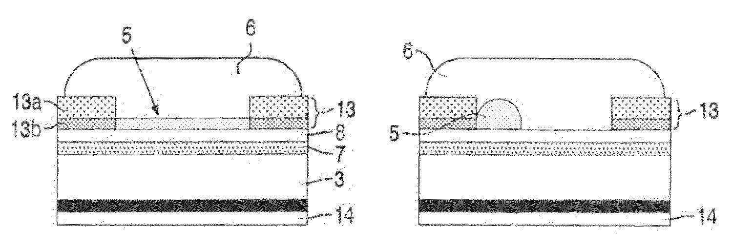
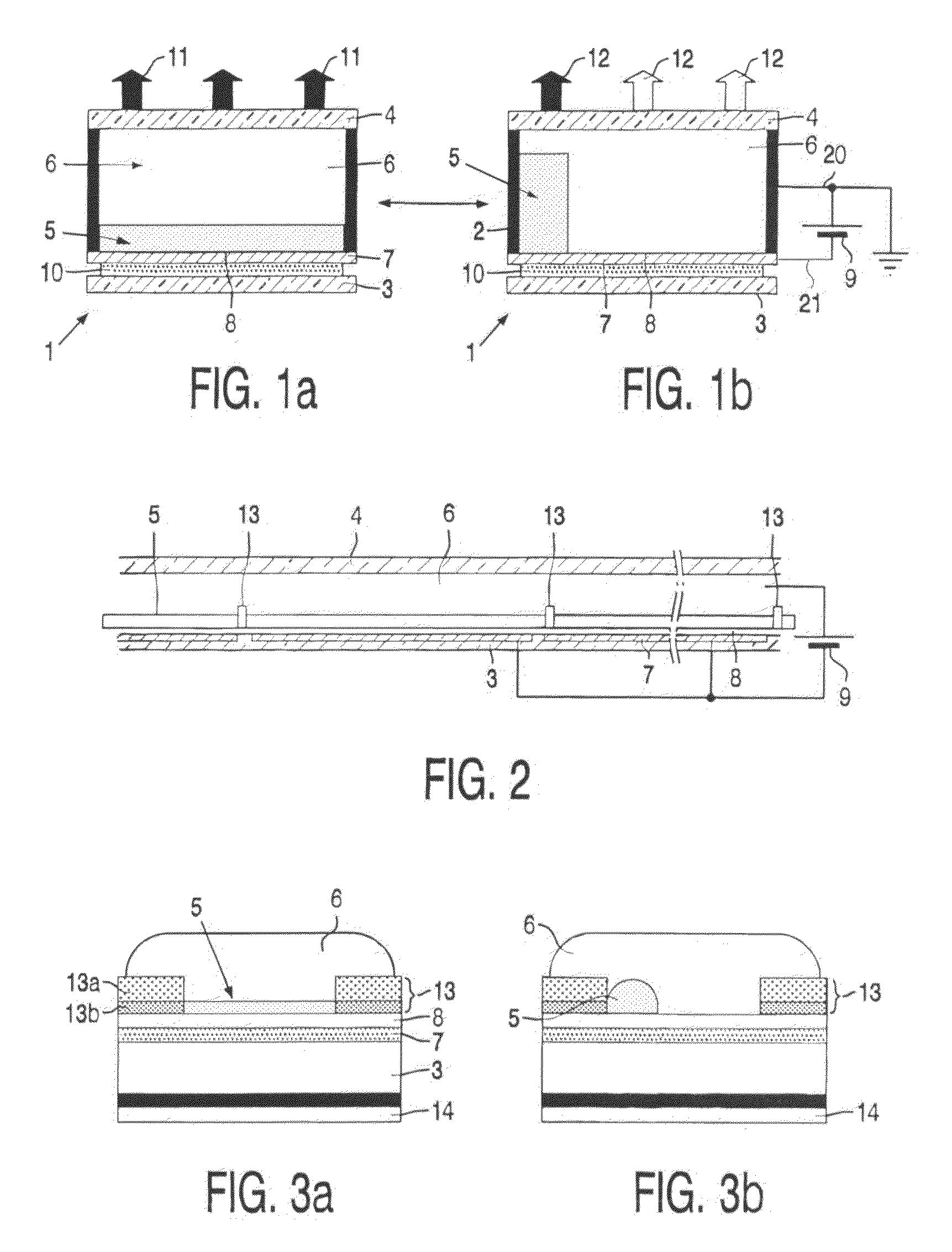
[0024]FIGS. 1a and 1b show a diagrammatic cross-section of a part of a display device 1 which shows the principle on which a display device according to the invention is based. Between two transparent substrates or support plates 3, 4 a first fluid 5 and a second fluid 6 are provided, which are immiscible with each other. The first fluid 5 is for instance an alkane-like hexadecane or as in this example a (silicone) oil. The second fluid 6 is electroconductive or polar, for instance water or a salt solution (e.g., a solution of KCl in a mixture of water and ethyl alcohol).

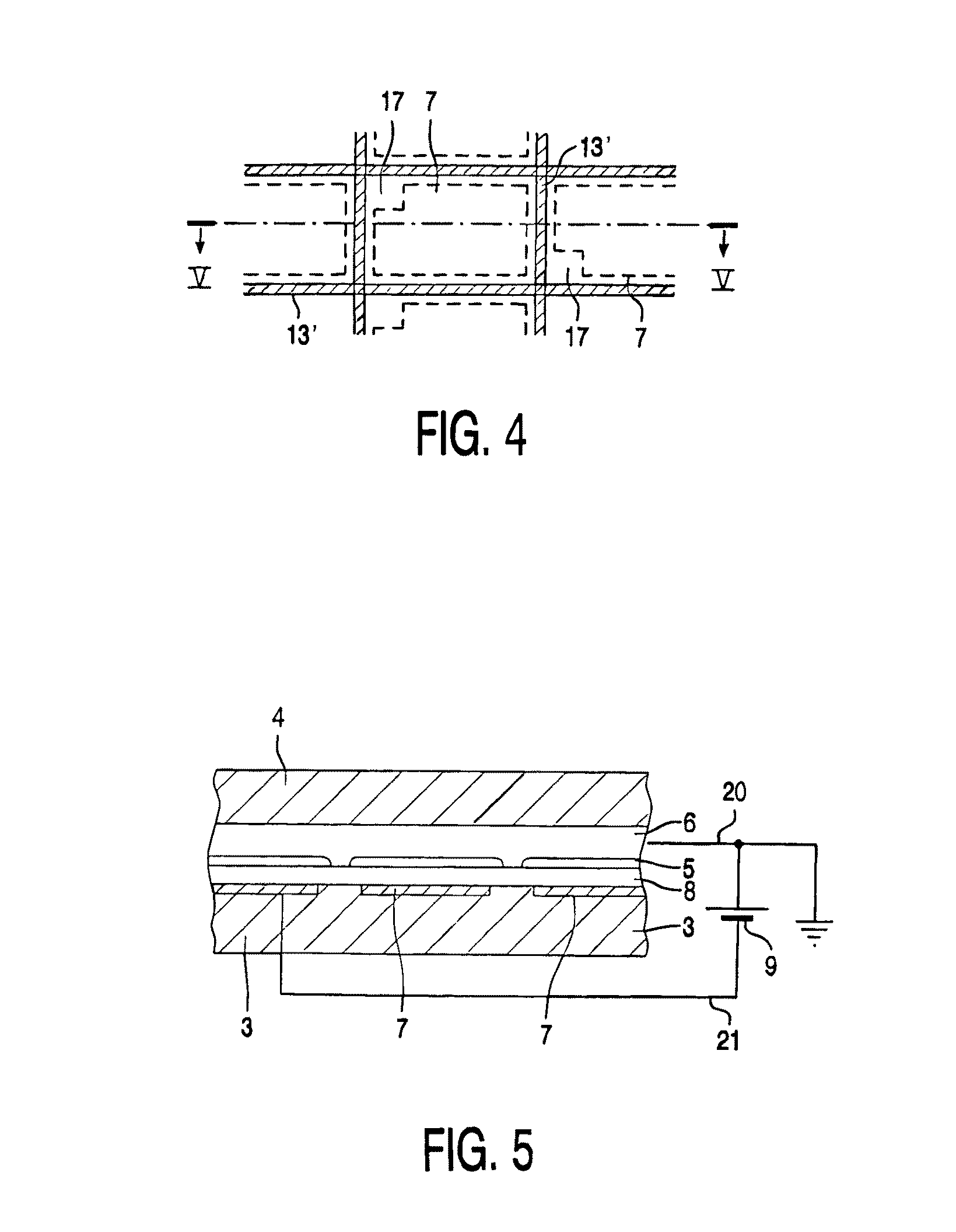
[0025]In a first state, when no external voltage is applied (FIG. 1a) the fluids 5, 6 adjoin the first and second transparent support plates 3, 4 of e.g. glass or plastic. On the first support plate 3 a transparent electrode 7, for example indium (tin) oxide is provided and an intermediate less wettable (hydrophobic) layer 8, in this example an amorphous fluoropolymer (AF1600).

[0026]When a voltage is applied (voltag...


PUM


Abstract

An optical switch, e.g., a display device based on layer break up or layer displacement having at least two different states, in which one of the fluids, e.g., oil in a first state, adjoins at least a first support plate and, in the second state, the other fluid at least partly adjoins the first support plate, in which picture elements are separated by areas having a hydrophilic surface.

Description

BACKGROUND[0001]1. Technical Field[0002]The invention relates to an optical switch comprising at least one first fluid and a second fluid immiscible with each other within a space between a first transparent support plate and a second support plate, the second fluid being electroconductive or polar.[0003]In particular the invention relates to a display device comprising picture elements (pixels) having at least one first fluid and a second fluid immiscible with each other within a space between a first transparent support plate and a second support plate, the second fluid being electroconductive or polar.[0004]2. Related Art[0005]Optical switches may be used in shutter applications, diaphragms, but also in switchable color filters in e.g. display applications.[0006]Display devices like TFT-LCDs are used in laptop computers and in organizers, but also find an increasingly wider application in GSM telephones. Instead of LCDs, for example, (polymer) LED display devices are also being u...

Claims


Application Information

Patent Timeline
Patent Type & Authority Patents(United States)
IPC IPC(8): G02B26/02G02B6/35
CPCG02B6/3538G02B26/005G02B26/02G02B26/08
Inventor HAYES, ROBERT A.FEENSTRA, BOKKE J.HAGE, LEENDERT M.WOLF, RONALD M.MORKS, EWOUT V.JAULNEAU, PATRICE G. C.CAMPS, IVO G. J.SCHLANGEN, LUCAS J. M.
Owner LIQUAVISTA BV
Why Eureka
Try Eureka