Semiconductor device and method of fabricating the same

a technology of semiconductor devices and semiconductors, applied in semiconductor devices, basic electric elements, instruments, etc., can solve the problems of inability to detect whether the electric fuse has been blown or not, the effect of improving the hold characteristic of the electric fus

Inactive Publication Date: 2009-05-05
RENESAS ELECTRONICS CORP
View PDF14 Cites 11 Cited by
  • Summary
  • Abstract
  • Description
  • Claims
  • Application Information

AI Technical Summary

Benefits of technology

[0019]Two fuse links contained in the electric fuse are connected in series in the semiconductor device of the present invention, so that the configuration allows detection of current after passing through two these fuse links. As a consequence, even if either one of two fuse links is accidentally re-connected, the electric fuse can be judged as being blown, if the other one remains disconnected. By virtue of this configuration, the electric fuse can considerably reduce the ratio of re-connection on the squared basis as compared with that of an electric fuse having only one fuse link. The ratio of re-connection referred to herein means a possibility of that an electric fuse once blown is undesirably detected as being connected, due to re-connection thereof. The semiconductor device of the invention can enhance the hold characteristic of the electric fuse therein.
[0020]Unlike the technology described in Japanese Laid-Open Patent Publication No. H11-297837, the present invention aims at reducing the ratio of re-connection of the electric fuse to a large degree, and to improve the hold characteristic. The ratio of re-connection is, however cannot be reduced, if only one of two fuse links is blown in the process of blowing the electric fuse. In order to reduce the ratio of re-connection, it is therefore necessary to respectively blow both of two fuse links. For the case where the fuse links are blown by supplying current to the electric fuse configured as having two fuse links connected in series, the current can no more flow through the electric fuse if either one of fuse links is blown. It is therefore necessary to configure the electric fuse so that, even after either one of the fuse links is blown, the current can flow through the other fuse link.
[0021]In the present invention, two fuse links are made different in readiness of blowing. As a consequence, the more-blowable fuse link can be blown by using the less-blowable fuse link as an interconnection, and by supplying current from the source line through the less-blowable fuse to the more-blowable fuse link. By virtue of provision of the terminal between the first fuse link and the second fuse link, the less-blowable fuse link can be blown by applying, using the terminal, voltage only to the less-blowable fuse link. In this way, two fuse links can independently be blown. Yield of disconnection can also be improved.
[0026]The present invention can therefore improve the hold characteristic of the electric fuse.

Problems solved by technology

However, use of a new apparatus for every product of a new generation results in endless increase in the production cost.
It was also found that the electric fuse has arisen some new problems.
Once such re-connection should occur, detection of whether the electric fuse has been blown or not cannot give a correct result, even if the electric fuse to be blown is once disconnected.

Method used


Image

  • Semiconductor device and method of fabricating the same
  • Semiconductor device and method of fabricating the same
  • Semiconductor device and method of fabricating the same

Examples


Embodiment Construction

[0035]The invention will be now described herein with reference to an illustrative embodiment. Those skilled in the art will recognize that many alternative embodiments can be accomplished using the teachings of the present invention and that the invention is not limited to the embodiment illustrated for explanatory purposes.

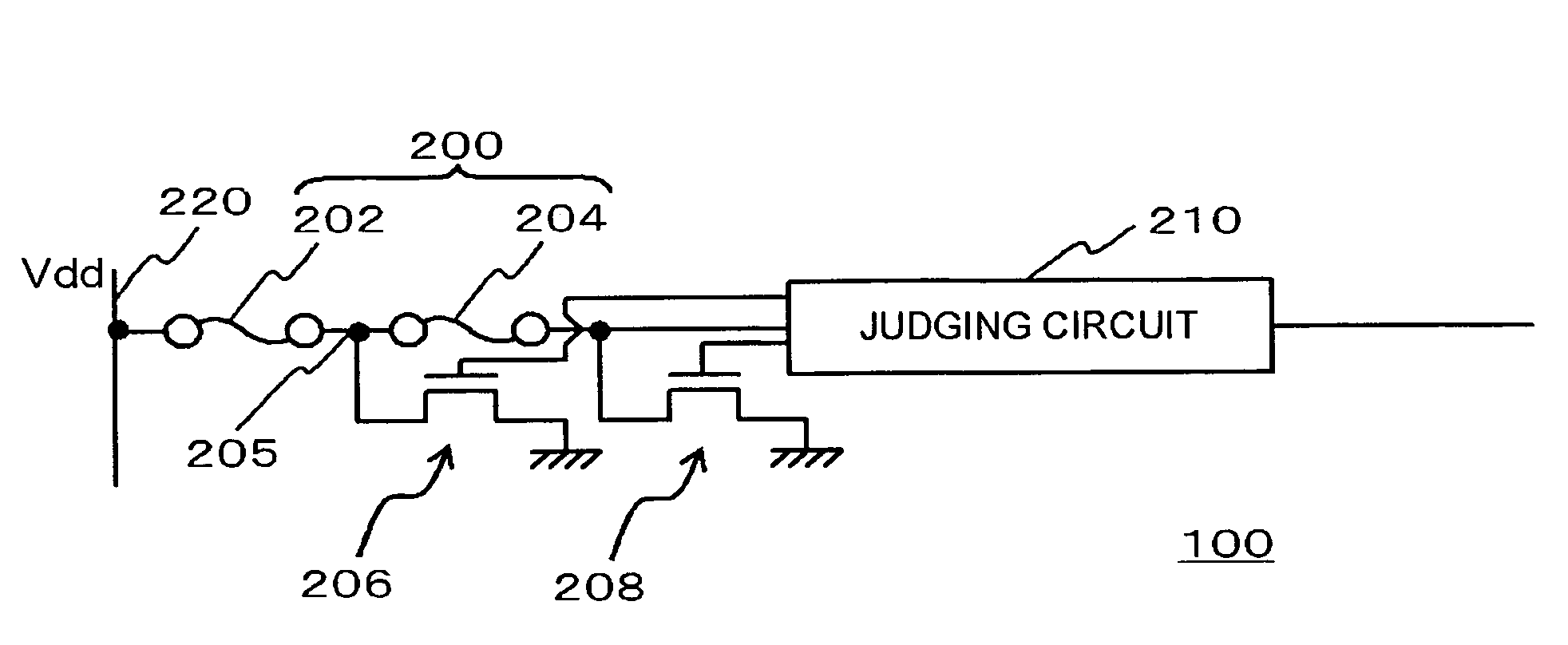
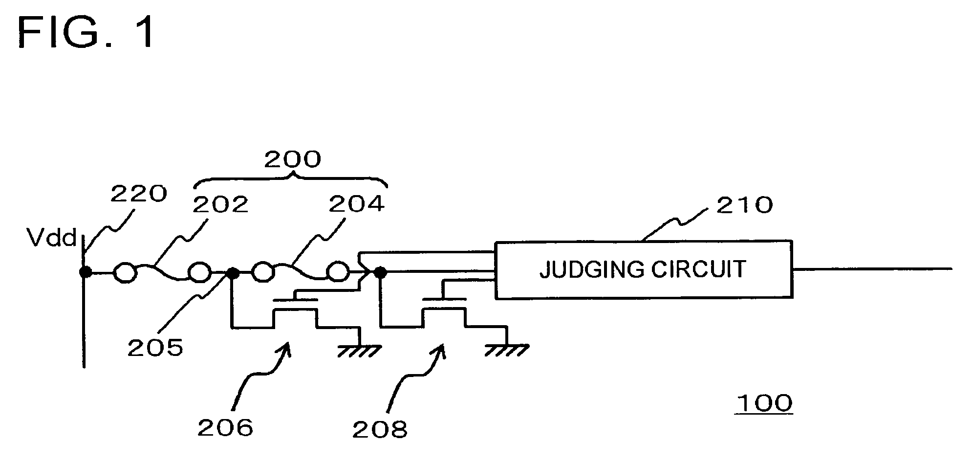
[0036]FIG. 1 is a circuit diagram showing a configuration of a semiconductor device containing an electric fuse in one embodiment of the present invention.

[0037]In this embodiment, a semiconductor device 100 contains a semiconductor substrate (not shown), an insulating film (not shown) formed on the semiconductor substrate, an electric fuse 200 formed thereon, a source line 220 connected to one end of the electric fuse 200, and a judging circuit 210 connected to the other end of the electric fuse 200. In this embodiment, the judging circuit 210 also has a function of a control circuit for transistors to be disconnected.

[0038]The electric fuse 200 contains a firs...


PUM


Abstract

The semiconductor device has a semiconductor substrate; an electric fuse provided on the semiconductor substrate, and having a first fuse link and a second fuse link connected in series; and a terminal provided between the first fuse link and the second fuse link, wherein the first fuse link and the second fuse link are configured as being different from each other in current value necessary for blowing.

Description

[0001]This application is based on Japanese patent application No. 2005-327248 the content of which is incorporated hereinto by reference.BACKGROUND[0002]1. Technical Field[0003]The present invention relates to a semiconductor device and a method of fabricating the same, and in particular to a semiconductor device containing an electric fuse and a method of fabricating the same.[0004]2. Related Art[0005]There has been known a technique of mounting a fuse on a semiconductor device, and blowing the fuse so as to adjust values of a resistor used for the semiconductor device, or to disconnect a nonconforming element for replacement with a normal element.[0006]Laser irradiation to a position of blowing of the fuse is one of known methods of blowing the fuse. Japanese Laid-Open Patent Publication No. H11-297837 discloses a technique of solving the problems below anticipated about the fuse blown by laser. That is, as the design rule of semiconductor devices shrinks, interconnections to be ...

Claims


Application Information

Patent Timeline
Patent Type & Authority Patents(United States)
IPC IPC(8): G11C17/18G11C5/06
CPCH01L23/5256H01L2924/0002H01L2924/00
Inventor UEDA, TAKEHIRO
Owner RENESAS ELECTRONICS CORP
Why Eureka
Try Eureka