Constant-velocity joint and image forming device

a constant speed, joint technology, applied in the direction of yielding couplings, electrographic process equipment, instruments, etc., can solve the problems of deteriorating image quality, difficult to precisely align the drum shaft and the rotary shaft of the motor, and the inability to rotate the photoconductor drum at a constant speed, etc., to prevent grease leakage, easy maintenance of the image forming device, and easy disassembly of the join

Inactive Publication Date: 2009-05-05
NTN CORP
View PDF9 Cites 76 Cited by
  • Summary
  • Abstract
  • Description
  • Claims
  • Application Information

AI Technical Summary

Benefits of technology

[0018]The synthetic resin is preferably an injection-moldable one so that the outer ring and / or the trunnion member that is made of the synthetic resin can be easily formed.
[0030]This eliminates the need for a boot for preventing leakage of grease, making it possible to assemble the constant-velocity joint simply by inserting the trunnion member into the bore of the outer ring and disassemble the joint simply by pulling the trunnion member out of the bore of the outer ring. Thus, maintenance of the image forming device is easy. Also, it is possible to completely eliminate the possibility of transfer materials being soiled with leaked grease. The image forming device produces less noise while torque is being transmitted through the constant-velocity joint.

Problems solved by technology

Such expansion and shrinkage of images deteriorates the quality of images.
In this arrangement, due to mounting errors when supporting the photoconductor drum and mounting the motor, it is extremely difficult to precisely align the drum shaft and the rotary shaft of the motor.
If the drum shaft and the rotary shaft are not aligned with or inclined relative to each other, it is impossible to rotate the photoconductor drum at a constant speed and thus to obtain high-quality images.
But because the joint used in the image forming device disclosed in JP patent publication 5-341589A is a nonconstant-velocity joint, it is impossible to rotate the photoconductor drum at a uniform speed.
Thus, even if the exposure position and the transfer position of the photoconductor drum are arranged so as to be diametrically opposite to each other, it is impossible to completely cancel out expansion and shrinkage of images because the diametrically opposed positions tend to shift due e.g. to assembling errors or inclination or deflection of the photoconductor drum, which in turn makes it impossible to form high-quality images.
Another problem is that the input and output members of the non-constant-velocity joint are not easily disassemblable, so that it is troublesome to replace parts of the image forming device such as the photoconductor drum.
Maintenance is thus difficult.
Although constant-velocity joints entirely made of a metal have sufficient strength, they are heavy, need lubrication with grease, and produce much noise during operation.
Thus, applications of such joints are limited.
For example, use of such joints in office machines, audio devices, medical devices and instruments and household appliances will be problematic.
Use of such joints in food processing devices machines is also problematic because in order to prevent foodstuffs from being contaminated with leaked lubricating grease, it is necessary to provide the joints with means for preventing leakage of grease such as a boot.
Such means naturally increases the number of parts and the size of the joints and pushes up their cost.
This makes maintenance of the image forming device difficult.

Method used


Image

  • Constant-velocity joint and image forming device
  • Constant-velocity joint and image forming device
  • Constant-velocity joint and image forming device

Examples


Embodiment Construction

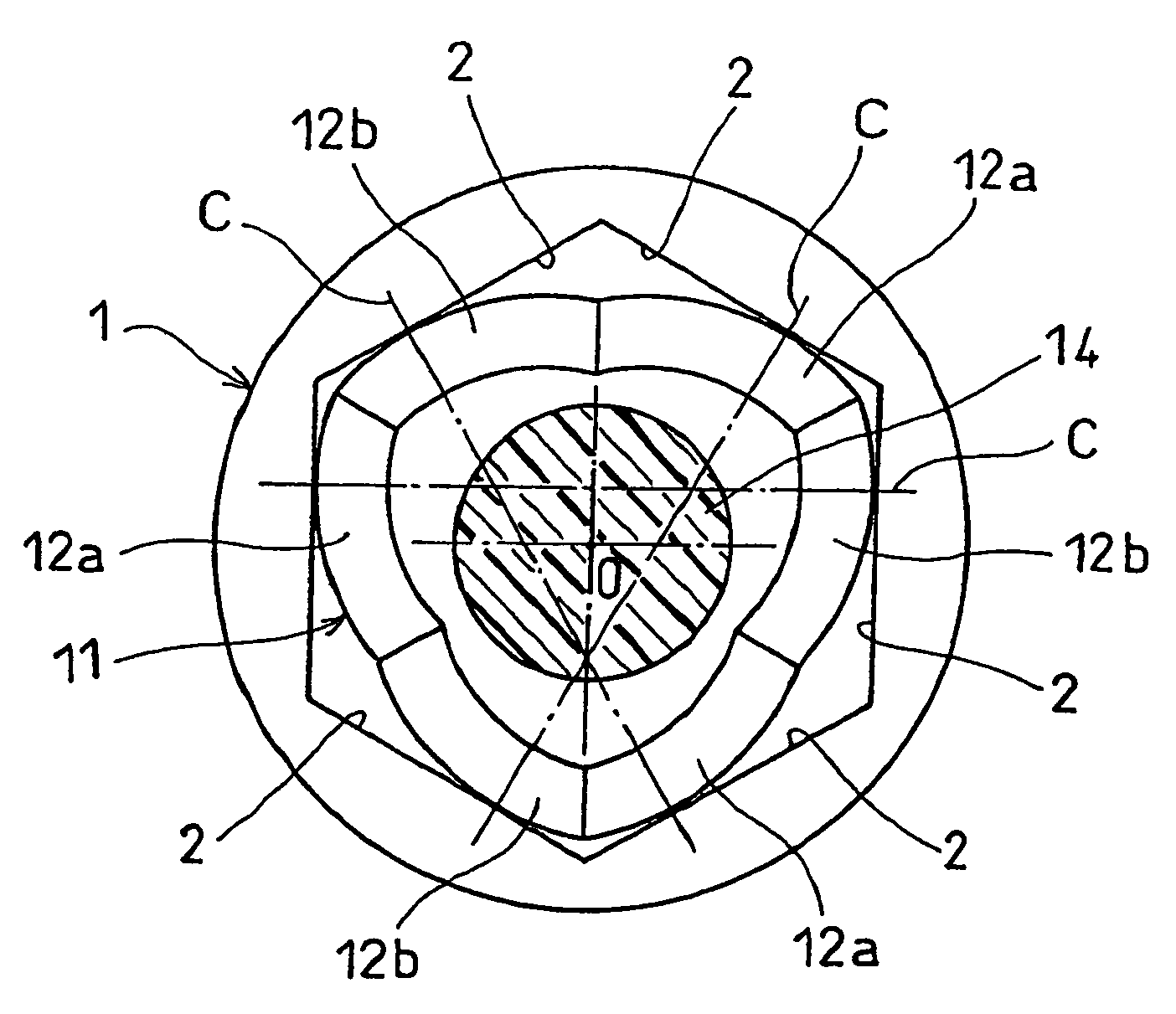
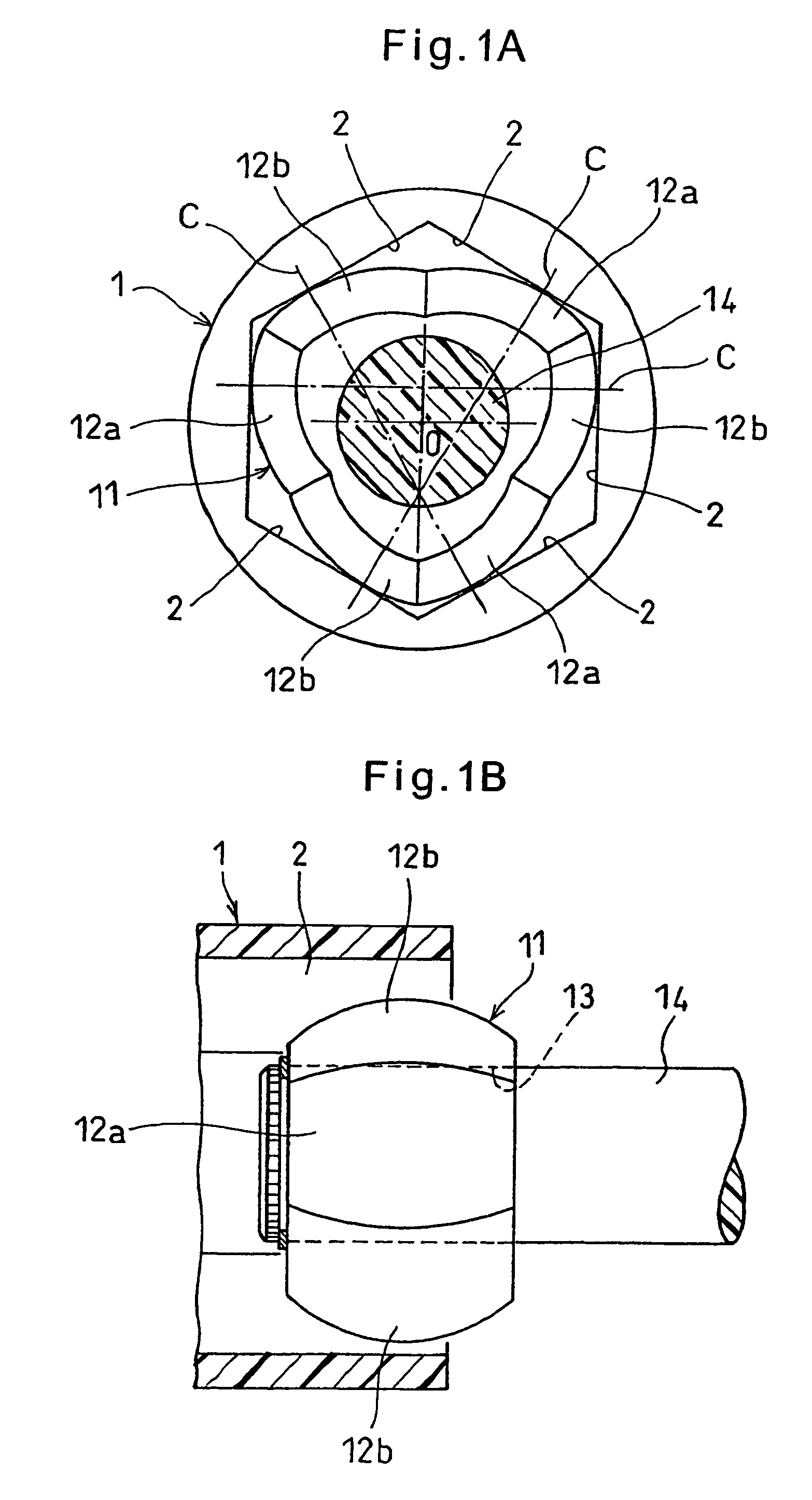
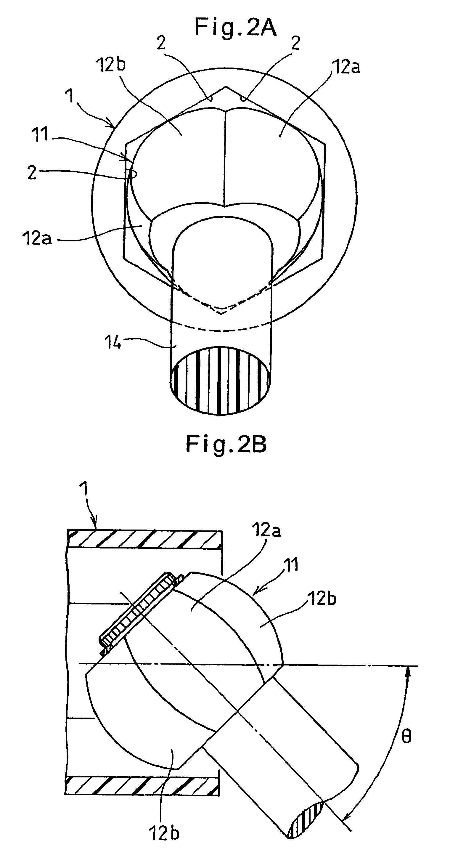
[0042]An embodiment of the present invention is now described. As shown in FIGS. 1A and 1B, the constant-velocity joint of the embodiment comprises an outer member 1 and a trunnion member 11. The outer ring 1 is formed with a regular hexagonal bore defined by six flat surfaces 2 that are parallel to the axis of the outer ring 1. The trunnion member 11 is inserted in this bore.

[0043]On its outer periphery, the trunnion member 11 has three circumferentially spaced apart first spherical surfaces 12a and three circumferentially spaced apart second spherical surfaces 12b circumferentially alternating with the first spherical surfaces 12a. The first and second spherical surfaces 12a and 12b are kept in contact with the respective flat surfaces 2.

[0044]The first spherical surfaces 12a each contact the corresponding flat surface 2 at a point offset in a circumferential direction (clockwise direction in FIG. 1A) from the circumferential center of the flat surface 2. The second spherical surf...


PUM


Abstract

A constant-velocity joint includes an outer ring formed with a bore defined by six flat surfaces parallel to its axis, and a trunnion member received in the bore of the outer ring. The trunnion member has an outer periphery formed with three first spherical surfaces circumferentially spaced apart from each other and three second spherical surfaces circumferentially spaced apart from each other and each disposed between adjacent first spherical surfaces. Each first spherical surface is in contact with one of the flat surfaces at a point offset from the circumferential center of the flat surface in one circumferential direction. Each second spherical surface is in contact with another flat surface at a point offset from the circumferential center of the flat surface in the other circumferential direction. At least one of the outer ring and the trunnion member is made of a synthetic resin.

Description

BACKGROUND OF THE INVENTION[0001]The present invention relates to a constant-velocity joint through which a driving shaft is connected to a driven shaft to transmit torque from the driving shaft to the driven shaft, and an image forming device such as a copier or a laser beam printer (LBP) in which a constant-velocity joint is used.[0002]A known image forming device includes a photoconductor drum which is rotated in one direction. Around the photoconductor drum, an electrifier, an exposure unit, a developing unit and a transfer / electrifier are provided. The electrifier uniformly charges the entire outer periphery of the photoconductor drum. Image light based on image information is thrown onto the thus charged outer periphery of the photoconductor drum by the exposure unit to form an electrostatic latent image thereon. Toner is supplied onto the latent image from the developing unit to form a toner image. The toner image is transferred onto a transfer material being fed at the same ...

Claims


Application Information

Patent Timeline
Patent Type & Authority Patents(United States)
IPC IPC(8): G03G15/00
CPCF16D3/185F16D2001/102
Inventor OHASHI, MASAAKISUGIYAMA, TATSUROKOBAYASHI, SHIGEOFUKUZAWA, SATORU
Owner NTN CORP
Why Eureka
Try Eureka