Quick pipe connector

Active Publication Date: 2009-05-12
YANG RICHARD
10 Cites 80 Cited by

AI-Extracted Technical Summary

Problems solved by technology

1. Since the connecting unit 12 includes four components 121˜124, the structure of the conventional quick pipe connector 1 is relatively complicated.
2. Six steps and a processing tool are required to assemble the conventional quick pipe connector 1, making the assembly process of the conventional quick pipe connector 1 relatively difficult.
3. Since contraction of the tubular housing 11 to form the first shoulder surface 111 is required to assemble the conventional quick pipe connector 1, the tubular housing 11 cannot be provided with screw threads on an outer surface thereof. Consequently, the conventional quick pipe connector 1 cannot facilitate connection of an outer cap around the tubular housing 11, thereby limiting the application of the conventional qu...

Method used

[0047]Referring back to embodiments of FIG. 3 and FIG. 4, the quick pipe connector may further include an anti-tamper ring 54 disposed removably between the end face 41 of the housing wall of the tubular housing 4 and the operating flange 532 of the release ring 53. The anti-tamper ring 54 prevents movement of the release ring 53 toward the end face 41 of the housing wall, i.e., the anti-tamper ring 54 prevents the release ring 53 from being disposed at the release position (shown in FIG. 6), when the anti-tamper ring 54 is disposed between the end face 41 of the housing wall and the operating flange 532 of the release ring 53. With further reference to FIG. 9, in this embodiment, the anti-tamper ring 54 includes a C-shaped body 541 clipped removably on the release ring 53, and two protrusions 542 extending radially and outwardly from opposite ends of the C-shaped body 541, respectively. The C-shaped body 541 is expanded slightly by pulling apart the protrusions 542 to facilitate removal of the anti-tamper ring 54 from the release ring 53. It should be noted herein that the anti-tamper ring 54 does not interfere with connecting of the quick pipe connector to the water pipe 23.
[0048]The locking ring 52, the release ring 53 and the tubular housing 4 are designed with dimensions that facilitate retention of the grip ring 51, the locking ring 52 and the release ring 53 inside the receiving space 400 in the tubular housing 4 under normal operating conditions. Therefore, the quick pipe connector of the present invention does not require the provision of threads or deformation of the tubular housing 4 to retain the grip ring 51, the locking ring 52 and the release ring 53 within the receiving space 400 in the tubular housing 4.
[0059]1. Since the connecting unit 5 may include only three components 51˜53, the structure of the quick pipe connector is relatively simple as compared to the prior art.
[0061]3. Since the locking ring 52, the release ring 53, and the tub...

Benefits of technology

[0021]Therefore, an object of the present invention is to provide a quick pipe connector that is relatively ...

Abstract

A quick pipe connector includes a tubular housing defining an axis, and a connecting unit. The connecting unit includes a grip ring adapted to grip a water pipe, and a locking ring abutting against a first housing shoulder surface of the tubular housing and positioning the grip ring to abut against a second housing shoulder surface of the tubular housing. The locking ring has a slit that extends parallel to the axis. An inner ring surface of the locking ring includes an annular inner shoulder part transverse to the axis. A release ring is formed with a stop surface confronting the annular inner shoulder part, and is movable along the axis relative to the locking ring to a release position, where the stop surface is moved away from the annular inner shoulder part and where the release ring forces the grip ring to release gripping action on the water pipe.

Application Domain

Sleeve/socket jointsPlug valves +3

Technology Topic

EngineeringShoulder surface

Image

  • Quick pipe connector
  • Quick pipe connector
  • Quick pipe connector

Examples

  • Experimental program(1)

Example

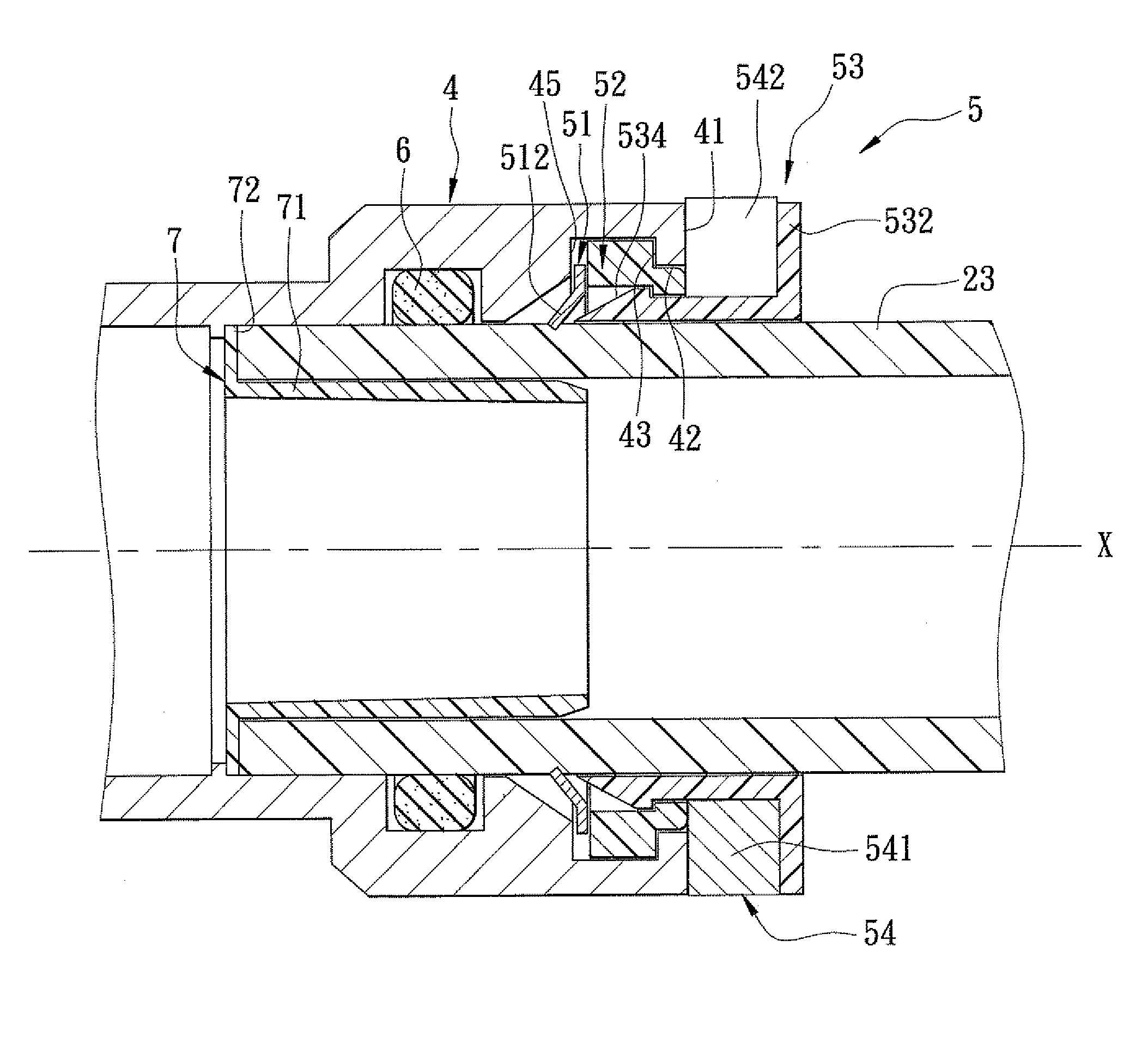
[0035]As shown in FIG. 3, FIG. 4 and FIG. 5, an embodiment of a quick pipe connector of the present invention is adapted for connecting to and disconnecting from a water pipe 23. The water pipe 23 can be made from one of cross-linked polyethylene (PEX), chlorinated polyvinyl chloride (CPVC), and copper (Cu), and can have pipe sizes ranging from ⅜″ to 2″ and the metric equivalents. The quick pipe connector includes a tubular housing 4, a connecting unit 5, a seal ring 6, and an inner support tube 7.
[0036]The tubular housing 4 includes a housing wall that defines an axis (X) and a receiving space 400 adapted for receiving an end portion of the water pipe 23. The housing wall has an end face 41, a first annular inner housing surface 42 connected to the end face 41, a second annular inner housing surface 44 disposed proximate to one end of the first annular inner housing surface 42 opposite to the end face 41 and having a radial dimension relative to the axis (X) that is larger than that of the first annular inner housing surface 42, a first housing shoulder surface 43 interconnecting the first and second annular inner housing surfaces 42, 44, a third annular inner housing surface 46 disposed proximate to one end of the second annular inner housing surface 44 opposite to the first housing shoulder surface 43 and having a largest radial dimension relative to the axis (X) that is smaller than that of the second annular inner housing surface 44, and a second housing shoulder surface 45 interconnecting the second and third annular inner housing surfaces 44, 46.
[0037]The connecting unit 5 includes a grip ring 51, a locking ring 52, and a release ring 53. The grip ring 51 is disposed in the receiving space 400 of the tubular housing 4 and is adapted to grip the end portion of the water pipe 23 in the receiving space 400. The locking ring 52 is disposed in the receiving space 400 such that the locking ring 52 abuts against the first housing shoulder surface 43 and positions the grip ring 51 in the receiving space 400 so that the grip ring 51 abuts against the second housing shoulder surface 45. The locking ring 52 has an outer ring surface 528, an inner ring surface 529 opposite to the outer ring surface 528 in radial directions relative to the axis (X), and a slit 526 extending parallel to the axis (X) from the inner ring surface 529 to the outer ring surface 528. The inner ring surface 529 includes an annular inner shoulder part 522 disposed transverse to the axis (X). The release ring 53 extends into the locking ring 52, is formed with a stop surface 533 that confronts the annular inner shoulder part 522 of the inner ring surface 529 of the locking ring 52, and is movable along the axis (X) relative to the locking ring 52 to a release position (as shown in FIG. 6), where the stop surface 533 is moved away from the annular inner shoulder part 522 of the inner ring surface 529 of the locking ring 52 and where the release ring 53 forces the grip ring 51 to release gripping action on the end portion of the water pipe 23 in the receiving space 400.
[0038]The seal ring 6 is disposed in the receiving space 400, and is adapted to abut sealingly against the end portion of the water pipe 23 in the receiving space 400.
[0039]The inner support tube 7 includes a support wall 71 adapted to be inserted into the end portion of the water pipe 23 received in the receiving space 400, and a support flange 72 extending radially and outwardly from the support wall 71 and adapted to abut against an end surface of the end portion of the water pipe 23.
[0040]In this embodiment, the housing wall of the tubular housing 4 further has an annular abutment surface 40 disposed in the receiving space 400 and spaced apart from the end face 41. The seal ring 6 is disposed in the receiving space 400 between the end face 41 and the annular abutment surface 40. The support flange 72 abuts against the annular abutment surface 40.
[0041]Moreover, the housing wall of the tubular housing 4 further has a fourth annular inner housing surface 48 disposed proximate to one end of the third annular inner housing surface 46 opposite to the second housing shoulder surface 45 and having a radial dimension relative to the axis (X) that is larger than the largest radial dimension of the third annular inner housing surface 46, a third housing shoulder surface 47 interconnecting the third and fourth annular inner housing surfaces 46, 48, and a fourth housing shoulder surface 49 connected to one end of the fourth annular inner housing surface 48 opposite to the third housing shoulder surface 46 and confronting the third housing shoulder surface 46. In addition, the seal ring 6 is disposed between the third and fourth housing shoulder surfaces 47, 49 of the housing wall, and abuts against the fourth annular inner housing surface 48.
[0042]Furthermore, the third annular inner housing surface 46 has a slanted part 461 extending radially and inwardly from the second housing shoulder surface 45 relative to the axis (X) away from the end face 41, and a connecting part 462 extending axially from one end of the slanted part 461 opposite to the second housing shoulder surface 45 to the third housing shoulder surface 47.
[0043]In addition, the grip ring 51 has an outer radial dimension smaller than the radial dimension of the first annular inner housing surface 42, and the largest radial dimension of the third annular inner housing surface 46 is smaller than the radial dimension of the first annular inner housing surface 42.
[0044]Additionally, the inner ring surface 529 of the locking ring 52 further has a first inner ring part 525 and a second inner ring part 527 with a radial dimension relative to the axis (X) smaller than that of the first inner ring part 525. The annular inner shoulder part 522 interconnects the first and second inner ring parts 525, 527. The outer ring surface 528 of the locking ring 52 has a first outer ring part 521, a second outer ring part 523 with a radial dimension relative to the axis (X) smaller than that of the first outer ring part 521, and an annular outer shoulder part 524 interconnecting the first and second outer ring parts 521, 523 and abutting against the first housing shoulder surface 43 of the housing wall.
[0045]In this embodiment, the grip ring 51 includes a flange portion 511 that is disposed in the receiving space 400 between the locking ring 52 and the second housing shoulder surface 45, and a plurality of claw portions 512 that extend inwardly in radial directions from the flange portion 511 toward the axis (X), that are slanted away from the locking ring 52, and that are adapted to grip the end portion of the water pipe 23 received in the receiving space 400.
[0046]The release ring 53 forces the claw portions 512 to move away from the end portion of the water pipe 23 when the release ring 53 is moved to the release position (shown in FIG. 6). In particular, the release ring 53 includes a surrounding wall 531 that is adapted to surround the end portion of the water pipe 23 received in the receiving space 400, and that has an urging surface 534, a sliding surface 535, and the stop surface 533. The urging surface 534 forces the claw portions 512 of the grip ring 51 to move away from the end portion of the water pipe 23 in the receiving space 400 when the release ring 53 is moved to the release position. The sliding surface 535 is disposed in slidable contact with the second inner ring part 527 of the inner ring surface 529 of the locking ring 52. The stop surface 533 interconnects the urging surface 534 and the sliding surface 535. The release ring 53 further includes an operating flange 532 that extends radially and outwardly from the surrounding wall 531, that is disposed externally of the locking ring 52 and the receiving space 400, and that is operable to move toward the end face 41 of the housing wall so as to dispose the release ring 53 at the release position (shown in FIG. 6). The urging surface 534 is an inclined surface extending in radial inward directions relative to the axis (X) away from the operating flange 532. In this embodiment, the release ring 53 has a diameter larger than an inner diameter of the locking ring 52 so that the locking ring 52 is slightly expanded when the release ring 53 extends into the locking ring 52.
[0047]Referring back to embodiments of FIG. 3 and FIG. 4, the quick pipe connector may further include an anti-tamper ring 54 disposed removably between the end face 41 of the housing wall of the tubular housing 4 and the operating flange 532 of the release ring 53. The anti-tamper ring 54 prevents movement of the release ring 53 toward the end face 41 of the housing wall, i.e., the anti-tamper ring 54 prevents the release ring 53 from being disposed at the release position (shown in FIG. 6), when the anti-tamper ring 54 is disposed between the end face 41 of the housing wall and the operating flange 532 of the release ring 53. With further reference to FIG. 9, in this embodiment, the anti-tamper ring 54 includes a C-shaped body 541 clipped removably on the release ring 53, and two protrusions 542 extending radially and outwardly from opposite ends of the C-shaped body 541, respectively. The C-shaped body 541 is expanded slightly by pulling apart the protrusions 542 to facilitate removal of the anti-tamper ring 54 from the release ring 53. It should be noted herein that the anti-tamper ring 54 does not interfere with connecting of the quick pipe connector to the water pipe 23.
[0048]The locking ring 52, the release ring 53 and the tubular housing 4 are designed with dimensions that facilitate retention of the grip ring 51, the locking ring 52 and the release ring 53 inside the receiving space 400 in the tubular housing 4 under normal operating conditions. Therefore, the quick pipe connector of the present invention does not require the provision of threads or deformation of the tubular housing 4 to retain the grip ring 51, the locking ring 52 and the release ring 53 within the receiving space 400 in the tubular housing 4.
[0049]According to this embodiment, the tubular housing 4 and the grip ring 51 are made from metal, the locking ring 52, the release ring 53 and the anti-tamper ring 54 are made from plastic, and the seal ring 6 is made from rubber.
[0050]Assembly of the quick pipe connector according to embodiments of the present invention includes the following steps:
[0051]1. The seal ring 6 is disposed in the receiving space 400 of the tubular housing 4 between the third and fourth shoulder surfaces 47, 49.
[0052]2. The inner support tube 7 is disposed in the receiving space 400 of the tubular housing 4 such that the support flange 72 of the inner support tube 7 abuts against the annular abutment surface 40 of the housing wall.
[0053]3. The grip ring 51 of the connecting unit 5 is disposed in the receiving space 400.
[0054]4. The locking ring 52 is contracted slightly and is then inserted into the receiving space 400 of the tubular housing 4.
[0055]5. The release ring 53 is extended into the locking ring 52, such that the locking ring 52 is slightly expanded, until the stop surface 533 confronts the annular inner shoulder part 522 of the inner ring surface 529 of the locking ring 52.
[0056]6. Optionally, the anti-tamper ring 54 is clipped on to the release ring 53 such that the anti-tamper ring 54 is disposed between the end face 41 of the housing wall of the tubular housing 4 and the operating flange 532 of the release ring 53.
[0057]Referring to FIG. 4 and FIG. 6, after the quick pipe connector is assembled, the end portion of the water pipe 23 may be inserted into the receiving space 400 of the tubular housing 4 such that an end surface of the end portion of the water pipe 23 abuts against the support flange 72 of the inner support tube 7. The release ring 53 is movable along the axis (X) relative to the locking ring 52 between a non-release position (shown in FIG. 4) and the release position (shown in FIG. 6). The end portion of the water pipe 23 is maintained in the receiving space 400 when the release ring 53 is disposed at the non-release position, where the urging surface 534 of the release ring 53 is spaced apart from the claw portions 512 of the grip ring 51, and where the end portion of the water pipe 23 is gripped by the claw portions 512. To move the release ring 53 to the release position, the operating flange 532 of the release ring 53 is operated to move toward the end face 41 of the housing wall such that the stop surface 533 is moved away from the annular inner shoulder part 522 of the inner ring surface 529 of the locking ring 52, and such that the urging surface 534 is disposed in contact with the claw portions 512 of the grip ring 51 and forces the claw portions 512 to move away from the end portion of the water pipe 23 in the receiving space 400. The end portion of the water pipe 23 may be removed from the receiving space 400 when the release ring 53 is disposed at the release position.
[0058]The quick pipe connector of the present invention has the following advantages:
[0059]1. Since the connecting unit 5 may include only three components 51˜53, the structure of the quick pipe connector is relatively simple as compared to the prior art.
[0060]2. Since only five steps may be used to assemble the quick pipe connector, and since no extra processing tool is required, the assembly process of the quick pipe connector is relatively easy and simple. In addition, without the step of disposing the inner support tube 7 in the receiving space 400 of the tubular housing 4, the assembly process is reduced to four steps.
[0061]3. Since the locking ring 52, the release ring 53, and the tubular housing 4 are designed with dimensions that facilitate retention of the grip ring 51, the locking ring 52 and the release ring 53 inside the receiving space 400 in the tubular housing 4 under normal operating conditions, unlike the prior art, embodiments of the quick pipe connector of the present invention does not require the provision of threads or deformation of the tubular housing 4 to retain the grip ring 51, the locking ring 52 and the release ring 53 within the receiving space 400 in the tubular housing 4.
[0062]4. Since the seal ring 6 is isolated from the connecting unit 5 by the third housing shoulder surface 47 of the housing wall of the tubular housing 4, damages caused by water pressure will not result in the connecting unit 5. Therefore, the quick pipe connector is relatively durable as compared to the prior art.
[0063]5. Since contraction of the tubular housing 4 is no longer required, damage to the connecting unit 5 caused by the contraction step is eliminated.
[0064]6. In the prior art, a structure similar to the operating flange 532 disclosed in the present invention cannot be provided on the release ring 123 of the conventional quick pipe connector 1 (as shown in FIG. 1) because doing so prevents the release ring 123 from being disposed in the outer locking ring 122. As such, the U-shaped pushing tool 22 is required to move the release ring 123 to the release position, making the conventional quick pipe connector 1 inconvenient to use. On the contrary, a user may operate the operating flange 532 directly to move the release ring 53 to the release position (shown in FIG. 6), making the quick pipe connector of embodiments of the present invention convenient to use.
[0065]7. The operating flange 532 of the release ring 53 not only provides a spot for labeling, but also provides a structural protection to the tubular housing 4. Therefore, the tubular housing 4 is protected from damages when the quick pipe connector is dropped on the floor.
[0066]It should be noted herein that the quick pipe connector may be formed into various kinds of connectors, including but not limited to T-joint connectors, valve connectors, pump connectors, etc., in other embodiments of the present invention. An example in which the quick pipe connector is formed into a ball valve is illustrated in FIG. 7 and FIG. 8. Since operations and functions related to the ball valve are identical to those disclosed hereinabove, further details of the same are omitted herein for the sake of brevity.
[0067]While the present invention has been described in connection with what is considered the most practical and preferred embodiment, it is understood that this invention is not limited to the disclosed embodiment but is intended to cover various arrangements included within the spirit and scope of the broadest interpretation so as to encompass all such modifications and equivalent arrangements.

PUM

no PUM

Description & Claims & Application Information

We can also present the details of the Description, Claims and Application information to help users get a comprehensive understanding of the technical details of the patent, such as background art, summary of invention, brief description of drawings, description of embodiments, and other original content. On the other hand, users can also determine the specific scope of protection of the technology through the list of claims; as well as understand the changes in the life cycle of the technology with the presentation of the patent timeline. Login to view more.

Similar technology patents

Photoelectric sensor for position of sun

InactiveCN101650173AEffective tracking range expandedSimple structure
Owner:WUHAN UNIV OF TECH

Magnetic cooling apparatus and control method thereof

ActiveUS20130180263A1simple structure
Owner:SAMSUNG ELECTRONICS CO LTD

Dual-Drivetrain of Power-Assist Vehicle

InactiveUS20100181130A1enhance uphill momentumsimple structure
Owner:CHOU WEN CHENG

Classification and recommendation of technical efficacy words

  • simple structure
  • easily assemble

Adaptor for reducing EMI

InactiveUS20050111796A1easily assemblereduce aperture
Owner:MOLEX INC

Capacitive Sensor and Method and Apparatus for Controlling a Pump Using Same

ActiveUS20080229819A1easily assemblereduce cost associate with assembly and/or material cost
Owner:WAYNESCOTT FETZER

Pouch-Equipped Intragastric Balloon

InactiveUS20080243166A1easily assemble
Owner:CIE EURO D'ETUDES & DE RECH DE DISPOSITIFS POUR L'IMPLANTATION PAR LAPAROSCOPIE

Component carrier

InactiveUS6995983B1less susceptibleeasily assemble
Owner:X2Y ATTENUATORS L L C

Collapsible pet housing

InactiveUS20050229866A1easily assembleeasy to clean
Owner:SIMPSON JEFFREY M
Why Eureka
Try Eureka