Multifunctional entry device for a downward flow tube reactor

a multi-functional, reactor technology, applied in auxillary pretreatment, furnaces, separation processes, etc., can solve the problems of need for catalyst control, inability to guarantee the non-occurrence of segregation of the catalyst stream, and the segregation of the mixture of the catalyst stream, so as to facilitate the maintenance of satisfactory mixing conditions

Inactive Publication Date: 2009-05-12
PETROLEO BRASILEIRO SA (PETROBRAS)
View PDF12 Cites 35 Cited by
  • Summary
  • Abstract
  • Description
  • Claims
  • Application Information

AI Technical Summary

Benefits of technology

[0021]It is a further object of the invention to facilitate maintenance of the satisfactory mixing conditions throughout the reaction zones of a downward tube reactor.
[0025]In order to improve the conditions of distribution of catalyst and to prevent the presence of hydrocarbon charge in the upper region of the device, which would give rise to undesirable coking, in the region between the entry valve and the collector / distributor vessel vapor may be injected by means of injector nozzles or by means of a ring. A further option, for improving the distribution of catalyst, is the use of a fluidization ring, inside the collector / distributor vessel, via which vapor is injected. Both options mentioned above may be used simultaneously.

Problems solved by technology

Another problem with the disclosure of this patent is the need for control of the catalyst volume, which is based on the pressure differential between the catalyst reservoir and the mixing chamber.
However, U.S. Pat. No. 4,919,898 concentrates on the mixing of catalyst with the hydrocarbon charge, and there is no guarantee as to the non-occurrence of segregation of the stream of catalyst from the stream of hydrocarbon after exit from the mixing chamber.
Actually, the performance of the device is affected by the geometrical interference of the shaft and of the plug of the valve installed inside the tube reactor, which will lead to segregation of the mixture of the stream of catalyst from the stream of hydrocarbon.
The redistribution ring, in the form proposed by this patent, does not guarantee satisfactory distribution of catalyst over the entire transverse section of the tube reactor; the use of charge-injection inlets forming an angle with the horizontal and with a component in the direction of the flow, i.e. in the downward vertical direction, does not permit the maintenance of a satisfactory distribution of the catalyst since the greater force component, owing to the inherent weight and to the velocity of the catalyst, is also in this direction.

Method used


Image

  • Multifunctional entry device for a downward flow tube reactor
  • Multifunctional entry device for a downward flow tube reactor
  • Multifunctional entry device for a downward flow tube reactor

Examples


Embodiment Construction

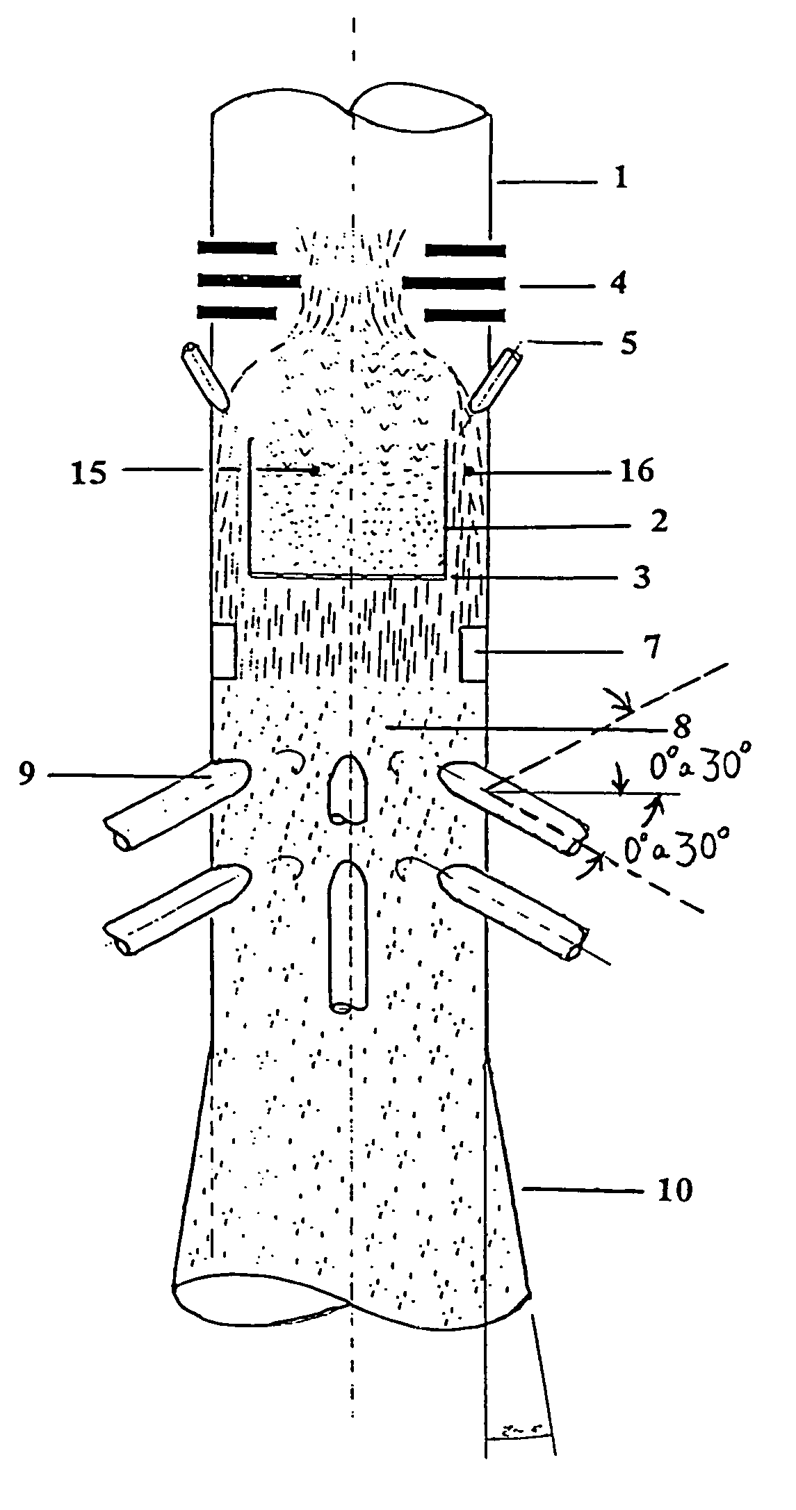
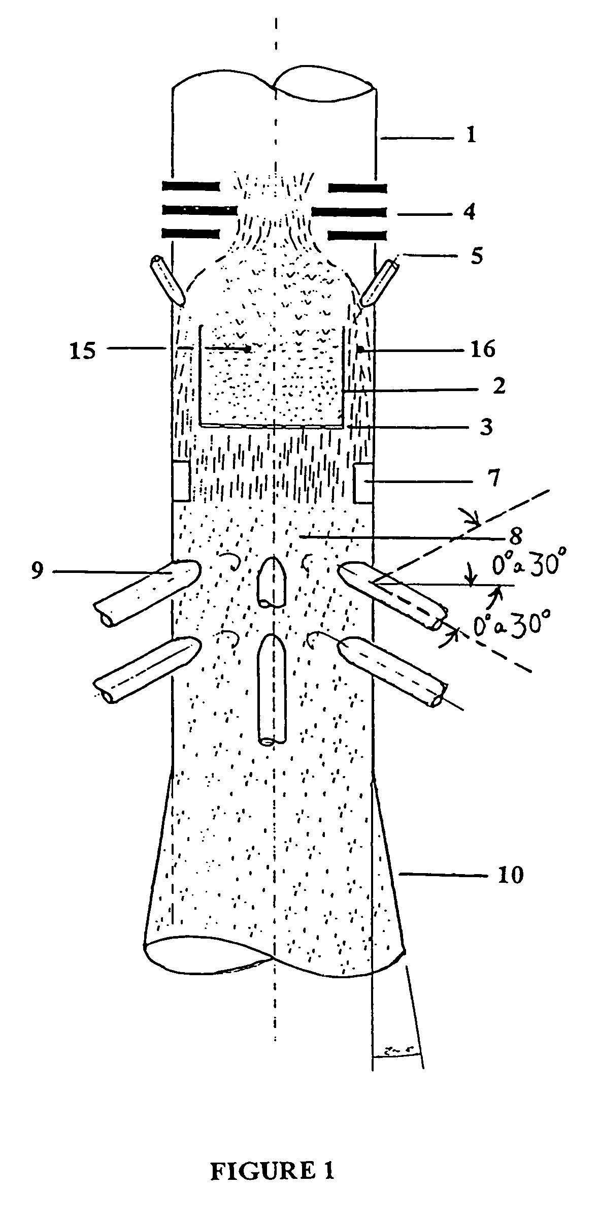
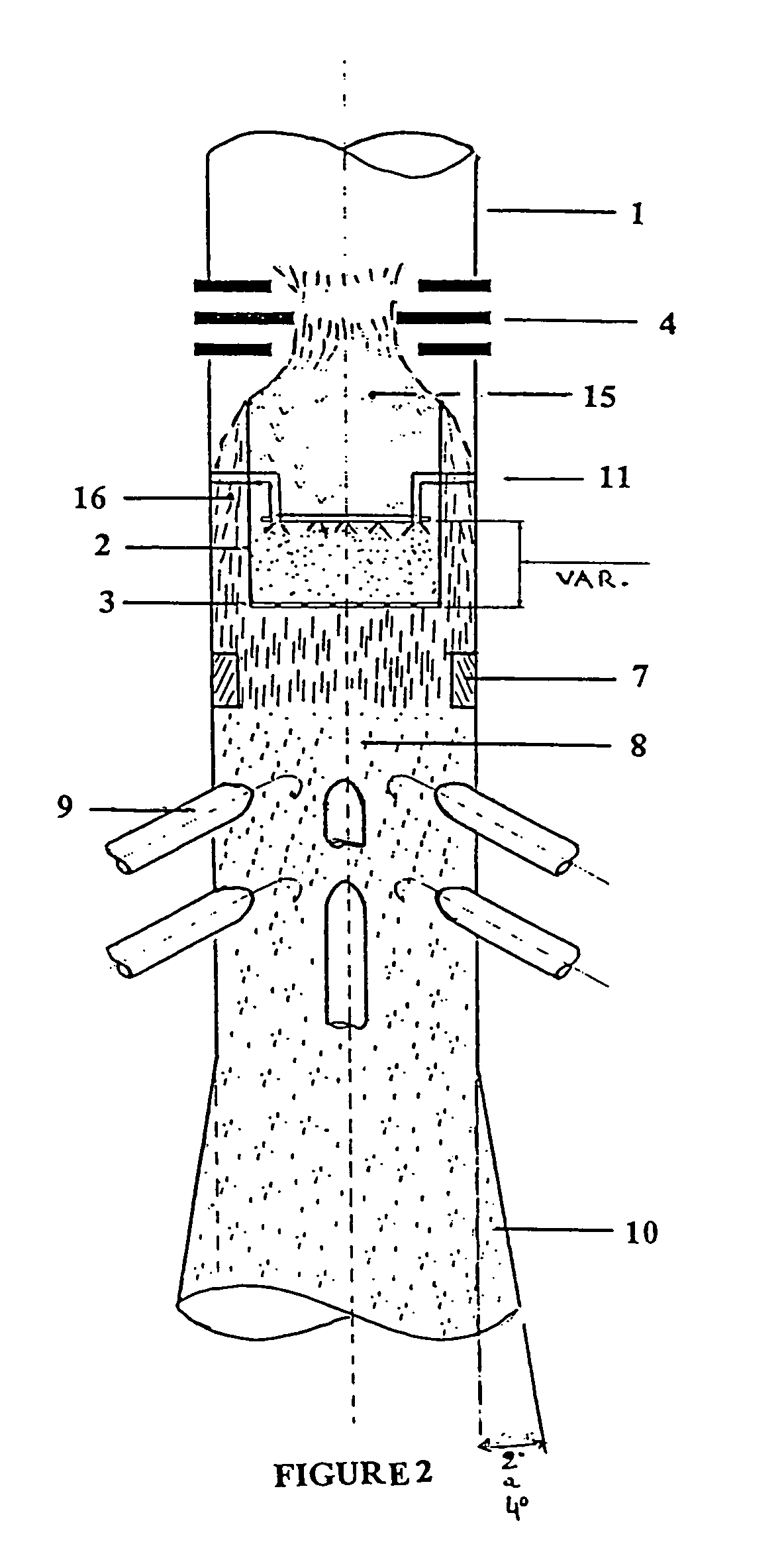
[0033]To enhance comprehension the invention will be described with reference to the accompanying drawings. However, the Figures diagrammatically illustrate merely variants of preferred embodiments of the invention and therefore are non-limiting in nature. The inventive concept to be described below having been obeyed, it will be obvious to those skilled in the art that it is possible to use other arrangements, complementary devices or modifications to the component design, within the scope of the invention as claimed herein.

[0034]The invention presents an entry device for use in downer-type vertical reactors for catalyst / hydrocarbon-charge ratios preferably in the range from 6 to 8, but the ratio may be below or above this range. A typical application would be, for example, in a unit processing from 5000 to 10000 m3 / day of gas oil or atmospheric residue (bottom product of the petroleum or crude-oil atmospheric distillation tower).

[0035]Two preferred embodiments of the invention and...


PUM

PropertyMeasurementUnit
angleaaaaaaaaaa
angleaaaaaaaaaa
angleaaaaaaaaaa

Abstract

A device and a method for operating it for application in a vertical tube reactor with downward flow (downer), has the aim of ensuring the intimate mixing of the solid particulate catalyst with a reagent fluid. Homogeneous distribution of catalyst is due to the use of a plate having perforations. Said perforated plate normally allows the passage of a portion of the stream of catalyst. The other portion overflows the edge of the plate, flowing in the form of an annular curtain, near the inner surface of the surrounding tube of the device. After passing beyond the perforated plate, the curtain-flow undergoes a deflection produced by an annular screen, to be mixed with the stream originating from the orifices in the perforated plate. A hydrocarbon charge is injected below the perforated plate, forming a certain angle with respect to the direction of the downward flow of catalyst, by means of inlets distributed uniformly about cross sections of the surrounding tube. After the mixing region, the diameter of the device, when smaller than the diameter of the associated tube reactor, expands slightly.

Description

CROSS-REFERENCES TO RELATED APPLICATIONS[0001]This application is a continuation of U.S. application Ser. No. 10 / 119,037, filed Apr. 10, 2002, now abandoned the entire content of which is incorporated by reference in this application.FIELD OF THE INVENTION[0002]The present invention relates to the area of petroleum refining.[0003]More specifically, the field of application of the invention is reactors used in fluid catalytic cracking (FCC) processes or other processes which make use of solid particulate catalyst.[0004]More particularly still, the invention relates to a device and to a method for supplying and homogeneously distributing solid particulate catalyst and for intimately mixing it with a reagent fluid, for application in a tube reactor with downward flow (downer).BACKGROUND OF THE INVENTION[0005]A fluid catalytic cracking (FCC) process aims to convert hydrocarbons with a high boiling point into lighter hydrocarbon fractions, such as gasoline and liquefied petroleum gas (LP...

Claims


Application Information

Patent Timeline
Patent Type & Authority Patents(United States)
IPC IPC(8): B01J8/18B01J8/00B01J8/12B01J8/24
CPCB01F5/205B01J8/003B01J8/065B01J8/1827B01J8/1872B01J8/1881B01J2208/00752B01J2208/00769B01J2208/0084B01F25/721
Inventor HUZIWARA, WILSON KENZOMARTIGNONI, WALDIR PEDROSILVA, MAURORAMOS, JOSE GERALDO FURTADODUBOIS, AURELIO MEDINAFREIRE, PAULO SERGIO
Owner PETROLEO BRASILEIRO SA (PETROBRAS)
Why Eureka
Try Eureka