Supercharge Your Innovation With Domain-Expert AI Agents!

Multilayered CMP stop for flat planarization

a technology of stop layer and planarization, which is applied in the direction of grinding/polishing apparatus, grinding machine, manufacturing tools, etc., can solve the problems of difficult control of planarization uniformity across the entire die or wafer, slurries that do not eliminate dishing, and non-planarity presents formidable problems for linewidth control and overetch budget, so as to achieve uniform polished surface

Inactive Publication Date: 2009-05-12
TEXAS INSTR INC
View PDF9 Cites 34 Cited by
  • Summary
  • Abstract
  • Description
  • Claims
  • Application Information

AI Technical Summary

Benefits of technology

This approach provides a more uniform polished surface by controlling the step height and reducing dishing, improving linewidth control and reducing manufacturing costs through optimized CMP processes.

Problems solved by technology

The planarization uniformity for many integrated circuits is difficult to control across the entire die or wafer.
Process irregularities such as pad conditioning, down force, and slurry delivery may also be a factor.
Such non-planarity presents formidable problems for linewidth control and overetch budgets in subsequent process steps.
High selective CMP slurries do not eliminate dishing due to pattern density difference.

Method used


Image

  • Multilayered CMP stop for flat planarization
  • Multilayered CMP stop for flat planarization
  • Multilayered CMP stop for flat planarization

Examples


Embodiment Construction

[0015]The invention will now be described in conjunction with forming shallow trench isolation. It will be apparent to those of ordinary skill in the art having reference to the specification that the benefits of the invention may be applied to other gap fill materials and applications.

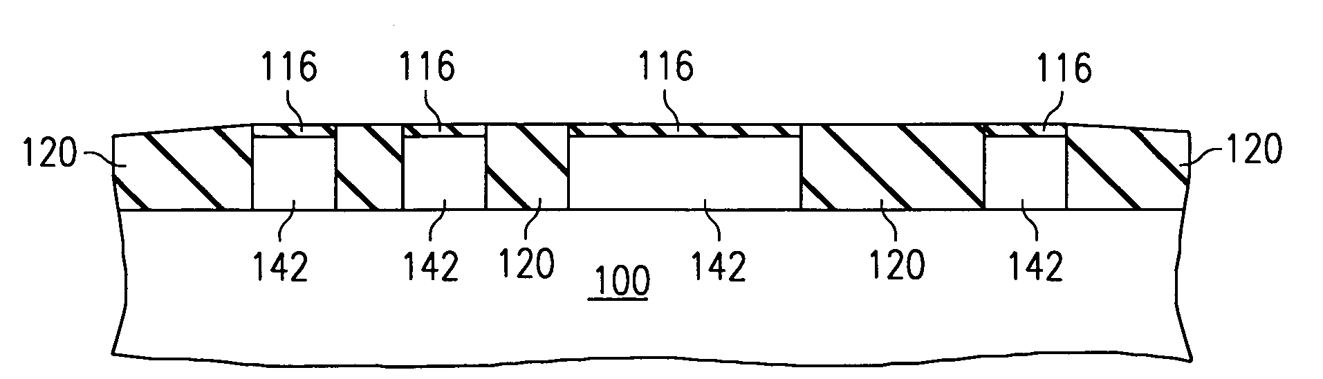
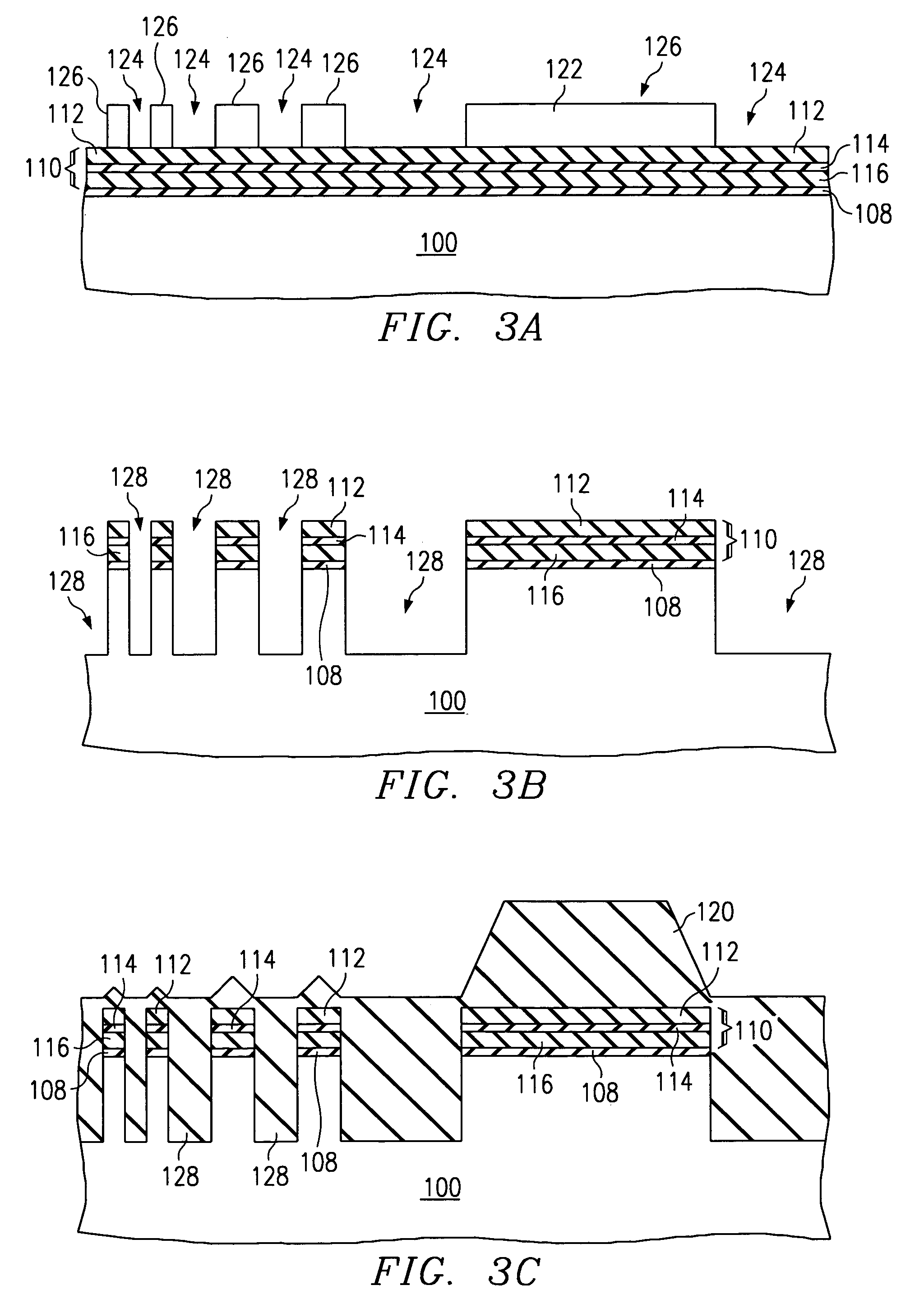
[0016]A polish stop 110 according to the invention is shown in FIG. 2. Polish stop 110 comprises at least three layers: film 112 / film 114 / film 116. Film 112's CMP erosion rate is lower than the CMP erosion rate for the gap fill material 120. The CMP selectivity of film 112 need not be greater than 5, although it can be. Film 114 is highly resistant to the strip etching of film 112. As an example, film 112 may be silicon nitride and film 114 may be silicon dioxide. The silicon nitride of film 114 may be stripped using phosphoric acid without removing the silicon oxide of film 114.

[0017]Film 116 may or may not comprise the same material as film 112. However, film 116 also has a CMP erosion rate lower th...


PUM


Abstract

A three layer film (116 / 114 / 112), such as nitride / oxide / nitride for a CMP stop layer (110). A gap filling material (120) is polished, stopping on the first film (112). The first film (112) is then stripped using an etch chemistry that is selective against removing the second film (114). CMP is then continued stopping on the third film (116).

Description

[0001]This is a divisional application of Ser. No. 09 / 997,882 filed Nov. 30, 2001 now U.S. Pat. No. 6,805,614 which is a nonprovisional application of provisional application No. 60 / 250,211 filed Nov. 30, 2000.FIELD OF THE INVENTION[0002]The invention is generally related to the field of chemical mechanical polishing (CMP) and more specifically to stopping layers for CMP.BACKGROUND OF THE INVENTION[0003]Chemical-mechanical polishing (CMP) for planarizing semiconductor wafers during fabrication is becoming more and more common. Two key areas in which CMP planarization is critical are shallow trench isolation (STI) and interconnect layers. A CMP system generally consists of a polishing pad, wafer carrier, and slurry. As a wafer carrier positions a semiconductor wafer against the polishing pad slurry is added between the polishing pad and the wafer. The wafer, the pad, or more typically, both are moved to planarize the surface of the wafer. CMP employs both a mechanical removal of mate...

Claims


Application Information

Patent Timeline
Patent Type & Authority Patents(United States)
IPC IPC(8): H01L21/336H01L21/4763H01L21/76B24B7/22H01L21/311H01L21/762
CPCH01L21/76229
Inventor KWOK, SIANG PING
Owner TEXAS INSTR INC
Features
  • R&D
  • Intellectual Property
  • Life Sciences
  • Materials
  • Tech Scout
  • Unparalleled Data Quality
  • Higher Quality Content
  • 60% Fewer Hallucinations
Learn More