Permanent-magnet generator
a permanent magnet generator and generator technology, applied in the direction of mechanical energy handling, magnetic circuit rotating parts, shape/form/construction, etc., can solve the problems of hysteresis loss and eddy current loss, certain the rotation variance of the generator itself adversely affects the shaft side, so as to reduce the quantity of rotation imbalance, reduce the quantity of balance correction processing, and improve the effect of rotation imbalan
- Summary
- Abstract
- Description
- Claims
- Application Information
AI Technical Summary
Benefits of technology
Problems solved by technology
Method used
Image
Examples
embodiment 1
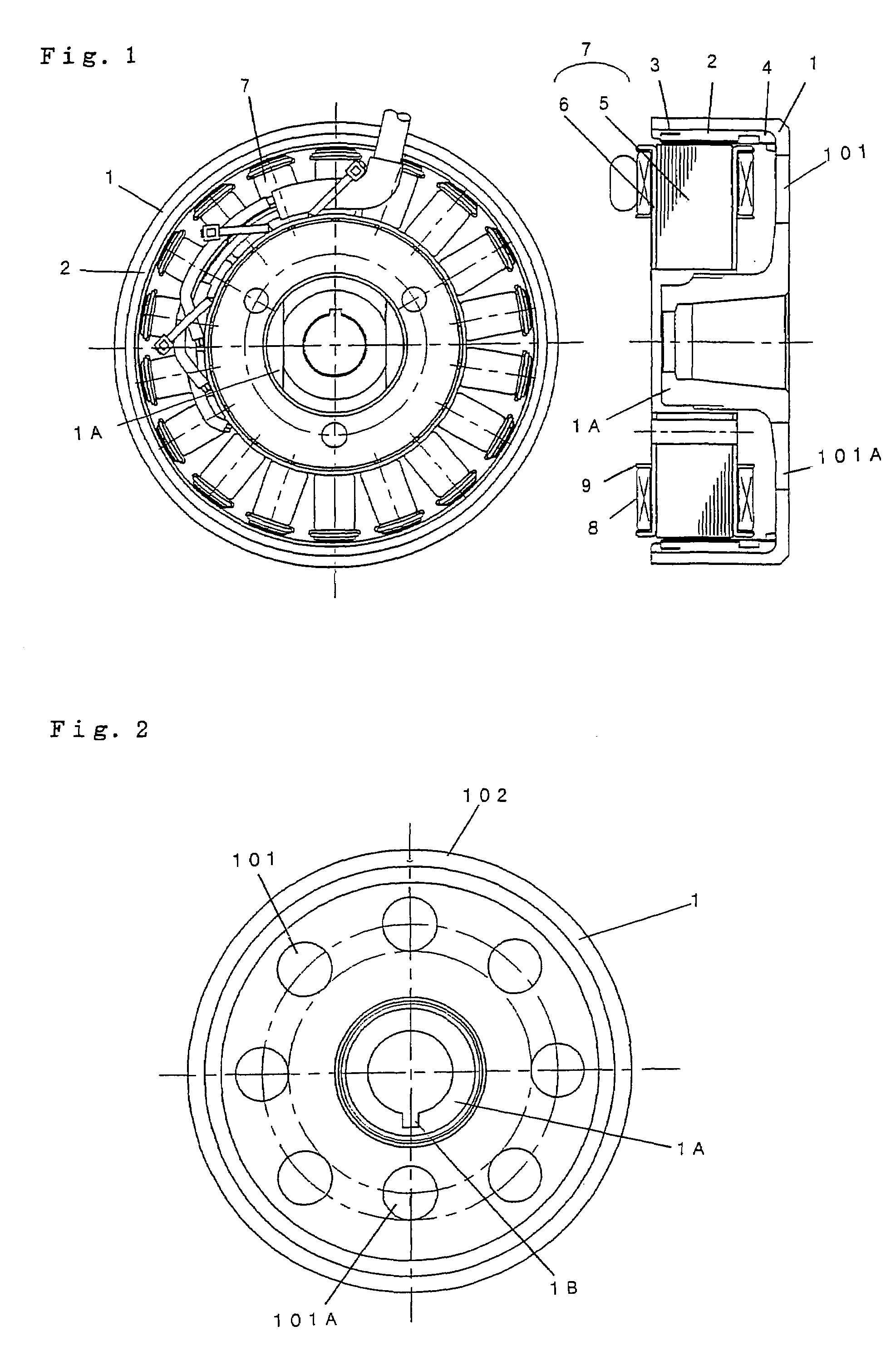
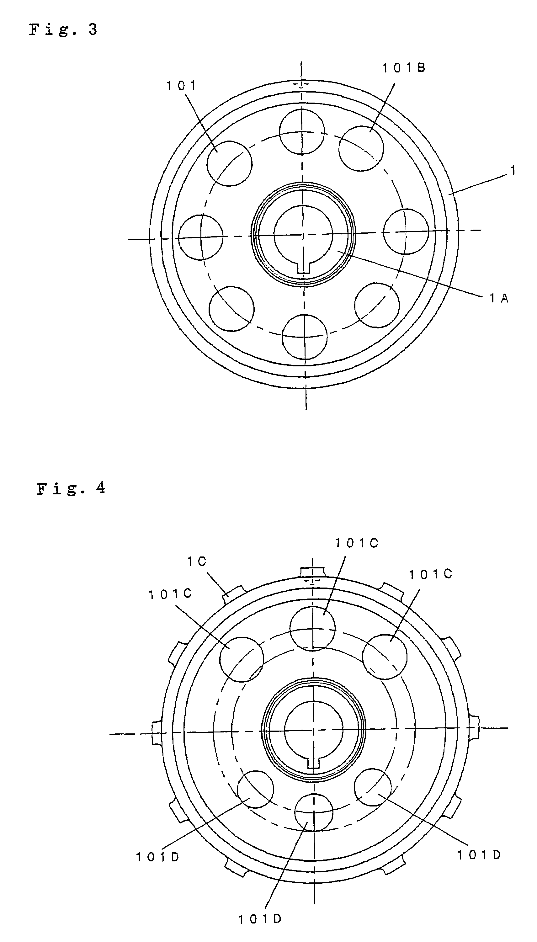
[0025]Embodiment 1 of this invention will now be described with reference to FIGS. 1 to 4.
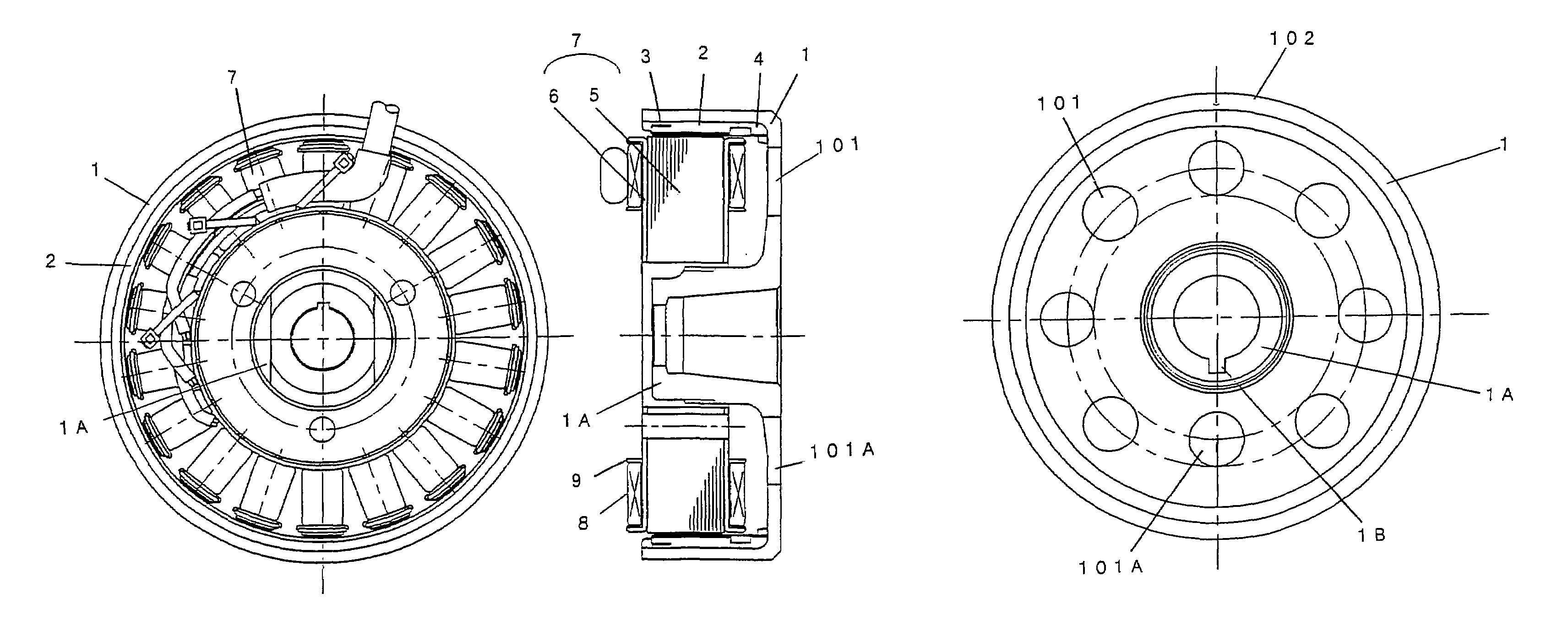
[0026]FIG. 1 is a plan view and longitudinal sectional view showing a permanent-magnet generator according to Embodiment 1. Numeral 1 represents a bowl-shaped fly wheel having a circumferential wall part and a bottom wall part. The fly wheel is produced by casting or hot forging. A boss part 1A having a key groove 1B formed therein is integrally formed at the center of the bottom wall part. The key groove 1B functions for connection with and rotation stop of a rotating shaft of an internal combustion engine or the like. The key groove 1B is processed at the center of the boss part 1A.
[0027]Numeral 2 represents plural magnets provided in the circumferential direction on the circumferential wall part of the fly wheel 1. Numeral 3 represents a cylindrical production ring adhering to and fitted with the inner side of the. circularly provided magnets 2. Numeral 4 represents a resin or mold material ...
embodiment 2
[0039]FIGS. 6 to 9 show a case of applying a fly wheel with a reduced thickness for reduction in size and weight, as Embodiment 2. Instead of vents, plural recessed parts 201 are arranged substantially circularly with spacing from each other on the inner surface of the bottom wall part of the fly wheel 1, and the shape or arrangement spacing (pitch) of at least one of the plural recessed parts 201 is made unequal in order to reduce the quantity of rotation imbalance including that caused by the key groove 1B.
[0040]FIG. 6 shows an example in which the shape of a recessed part 201A facing the key groove 1B, which is one of the recessed parts. FIG. 7 shows an example in which the arrangement spacing (pitch) of a recessed part 201B, which is one of the recessed parts, is changed. FIG. 8 shows an example in which the area of a recessed part 201C, which is one of the recessed parts, is increased. FIG. 9 shows an example in which an inclined surface 1F is formed at the bottom of a recessed...
PUM
 Abstract
Description
Claims
Application Information
 - R&D
- Intellectual Property
- Life Sciences
- Materials
- Tech Scout
- Unparalleled Data Quality
- Higher Quality Content
- 60% Fewer Hallucinations
Browse by: Latest US Patents, China's latest patents, Technical Efficacy Thesaurus, Application Domain, Technology Topic, Popular Technical Reports.
© 2025 PatSnap. All rights reserved.Legal|Privacy policy|Modern Slavery Act Transparency Statement|Sitemap|About US| Contact US: help@patsnap.com


