Measuring electrode system

a technology of measuring electrodes and electrodes, applied in the field of measuring electrode arrangements, can solve problems such as unsatisfactory electric contact of measurement objects

Inactive Publication Date: 2009-05-12
VYAIRE MEDICAL GMBH
View PDF21 Cites 9 Cited by
  • Summary
  • Abstract
  • Description
  • Claims
  • Application Information

AI Technical Summary

Benefits of technology

[0004]The object of this invention is therefore to create a measuring electrode arrangement that is especially suitable for electroimpedance tomography and permits the best possible electric contacting of the measurement object.
[0005]This invention includes the general technical teaching of integrating a supply space for a contact medium into the measuring electrode arrangement, whereby the contact medium reduces the electric contact resistance between the measuring electrode and the object of measurement.
[0011]Multiple electric shields are preferably provided here and are electrically insulated with respect to one another and the individual measuring electrodes. Such an arrangement with multiple separate electric shields offers the possibility of having an electric signal act on the shields to improve the shielding effect. With use of a measuring electrode as a stimulation electrode, the respective shield may be acted upon by an electric signal in a targeted way, said signal compensating for the interfering field caused by the stimulation.
[0013]In the inventive measuring electrode arrangement, the shield is preferably arranged on the side of the measuring electrode facing away from the measurement object in order to achieve the best possible shielding effect.

Problems solved by technology

The measuring electrodes must be positioned as accurately as possible here and their positions must be maintained with the greatest possible accuracy during the measurement process, because improper positioning of the measuring electrodes would distort the result of the measurement.
One disadvantage of the known measuring electrode arrangements for electroimpedance tomography is therefore the unsatisfactory electric contacting of the measurement object.

Method used


Image

  • Measuring electrode system
  • Measuring electrode system
  • Measuring electrode system

Examples


Embodiment Construction

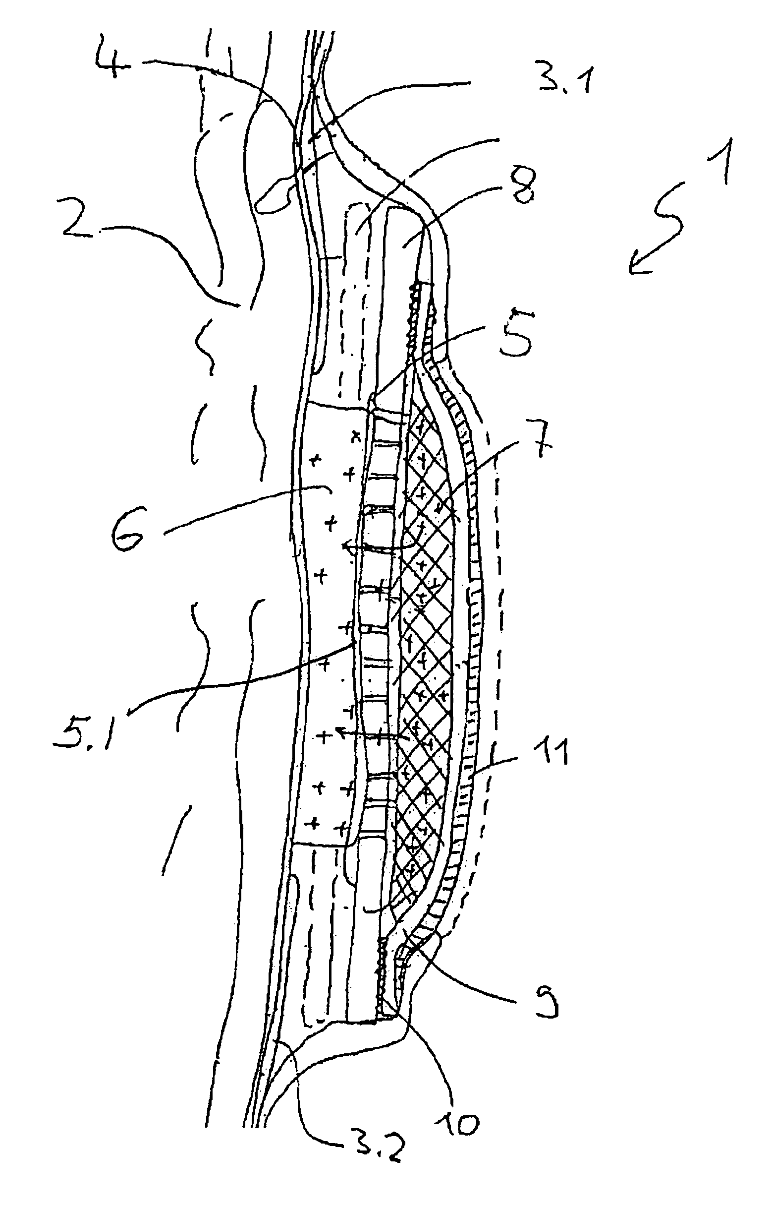
[0021]The measuring electrode arrangement 1 shown in FIG. 1 is used for electric contacting of a patient's chest 2 in electroimpedance tomography.

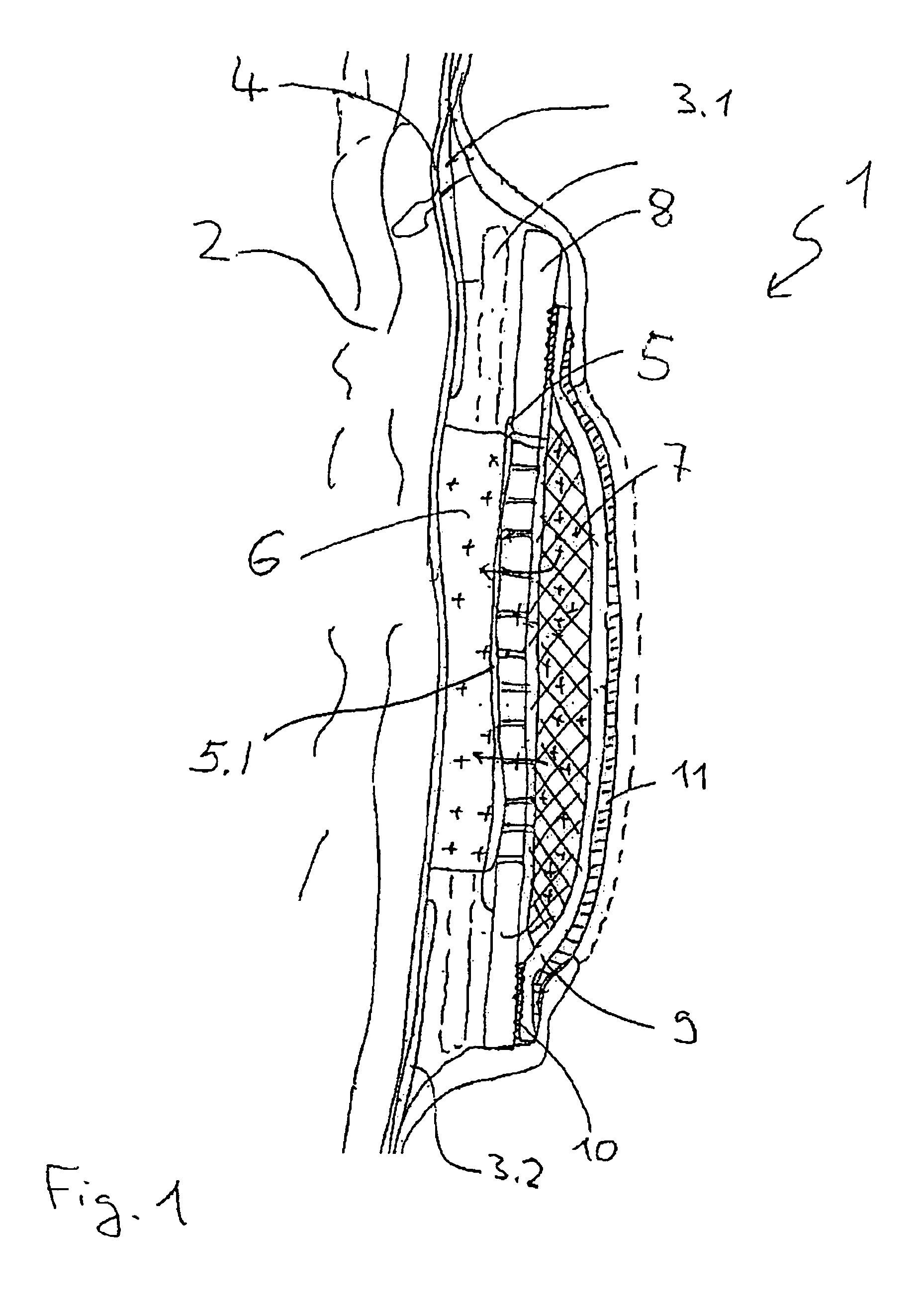
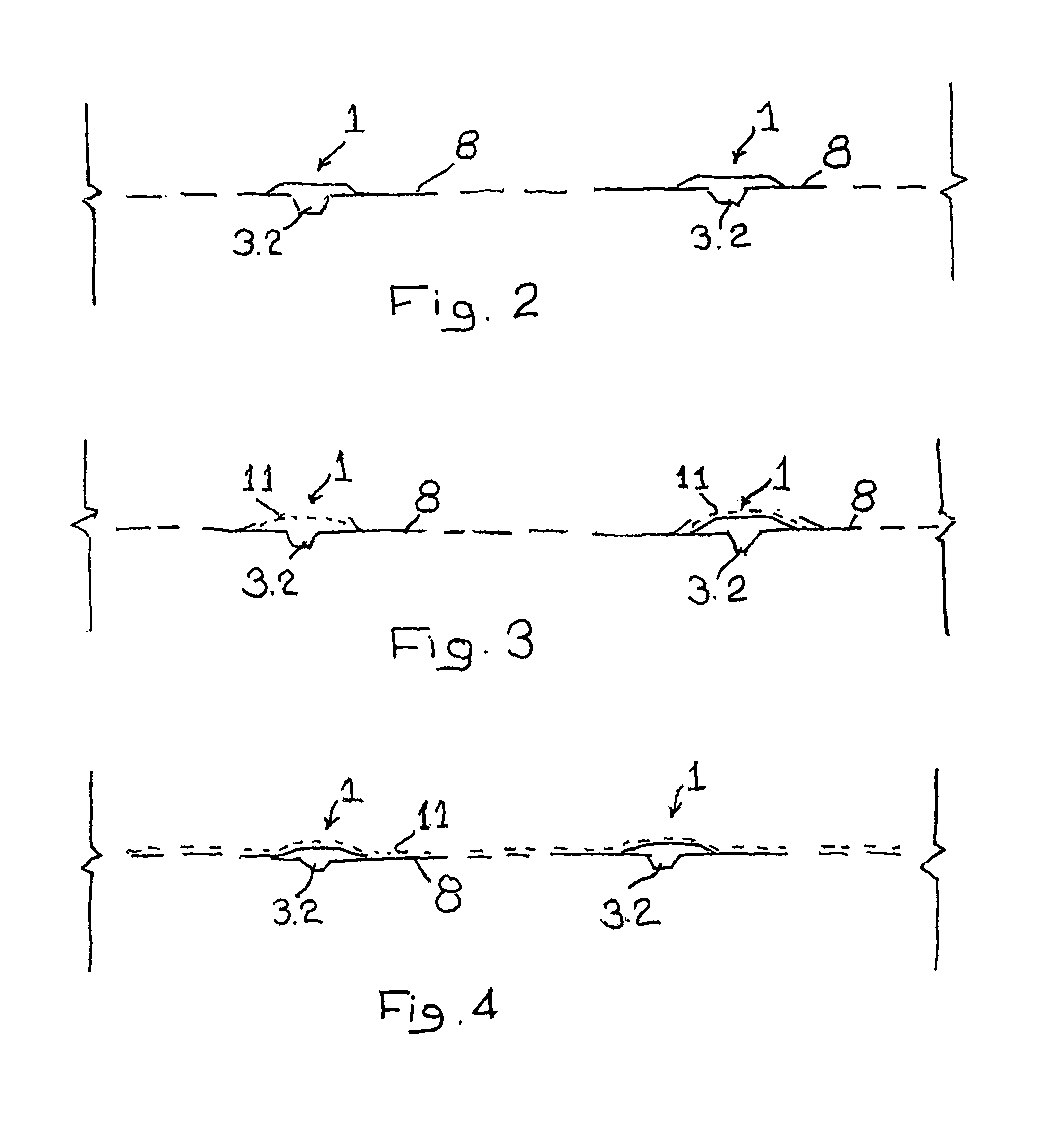
[0022]The electrode arrangement is currently designed in the form of a belt which is placed around the patient's chest 2 and attached to the patient's skin surface 4 by two strips of adhesive tape 3.1, 3.2. This mechanical attachment of the electrode arrangement on the body surface 4 prevents the placement of the measuring electrode arrangement 1 during one electroimpedance tomography procedure or between multiple successive tomography procedures from changing, which would distort the measurement result.

[0023]Several measuring electrodes are distributed over the circumference of the patient's chest 2 in the measuring electrode arrangement 1, but only one measuring electrode 5 is depicted in the cross-sectional view. The measuring electrode 5 here is not in direct contact with the body surface 4 but instead is arranged at a distance from th...


PUM


Abstract

This invention relates to a measuring electrode arrangement (1), in particular for electroimpedance tomography, having at least one measurement object (5) for electric motor contacting of a measurement object (2). It is proposed that a storage space (7) which contains a contact medium (6) for reducing the electric contact resistance between the measuring electrode (5) and the measurement object (2) is located on the side of the measuring electrode (5) facing away from the measurement object (2), said storage space containing a contact medium (6) for reducing the electric contact resistance between the measuring electrode (5) being at least partially permeable for the contact medium (6).

Description

FIELD OF THE INVENTION[0001]This invention relates to a measuring electrode arrangement, in particular for electroimpedance tomography.BACKGROUND OF THE INVENTION[0002]To perform so-called electroimpedance tomography (EIT) on a patient, several measuring electrodes must be attached to the patient's body part that is to be examined, e.g., the patient's chest. The measuring electrodes must be positioned as accurately as possible here and their positions must be maintained with the greatest possible accuracy during the measurement process, because improper positioning of the measuring electrodes would distort the result of the measurement. In addition, the measuring electrodes must make electric contact as well as possible with the part of the body to be examined, i.e., the contact resistance between the measuring electrodes and the parts of the body to be examined should be as low as possible and must not fluctuate during the measurement process.[0003]Therefore, measuring electrode ar...

Claims


Application Information

Patent Timeline
Patent Type & Authority Patents(United States)
IPC IPC(8): A61B5/04A61B5/05A61B5/053A61N1/05A61N1/30H01R3/08
CPCA61B5/0536A61B5/6831A61B2562/043
Inventor EICHLER, RUEDIGER
Owner VYAIRE MEDICAL GMBH
Why Eureka
Try Eureka