Apparatus and method for reducing electromigration

a technology of electromigration and apparatus, applied in the field of apparatus and method for reducing electromigration, can solve the problems of non-trivial distance between dendrites of components, exacerbate problems, and so as to reduce reduce the high bias “on” time. , the effect of reducing the probability of dendrite formation

Inactive Publication Date: 2009-05-12
MAGNOLIA LICENSING LLC
View PDF15 Cites 3 Cited by
  • Summary
  • Abstract
  • Description
  • Claims
  • Application Information

AI Technical Summary

Benefits of technology

[0006]An apparatus and method therefor wherein instead of applying a high bias voltage 100 per cent of the time to leads susceptible to dendrite formation, the bias voltage is switched from a low bias voltage to a high voltage bias mode when the leads are to be read or scanned by a microprocessor, and the bias voltage is then switched back to a low bias voltage mode when the lines are not being read, e.g., at other times, thereby greatly reducing the high bias “on” time and dramatically reducing the probability of dendrite formation.
[0007]The reduction of high bias voltage “on” time is accomplished by progr

Problems solved by technology

The dendrite formation caused by these metallic dendritic bridges develops over a period of time and may eventually extend between the printed circuit board traces, particularly if the traces are close to each other and/or are unplated copper, because copper is a particularly susceptible metal well known for having electromigration problems.
This had proved to

Method used


Image

  • Apparatus and method for reducing electromigration
  • Apparatus and method for reducing electromigration
  • Apparatus and method for reducing electromigration

Examples


Embodiment Construction

)

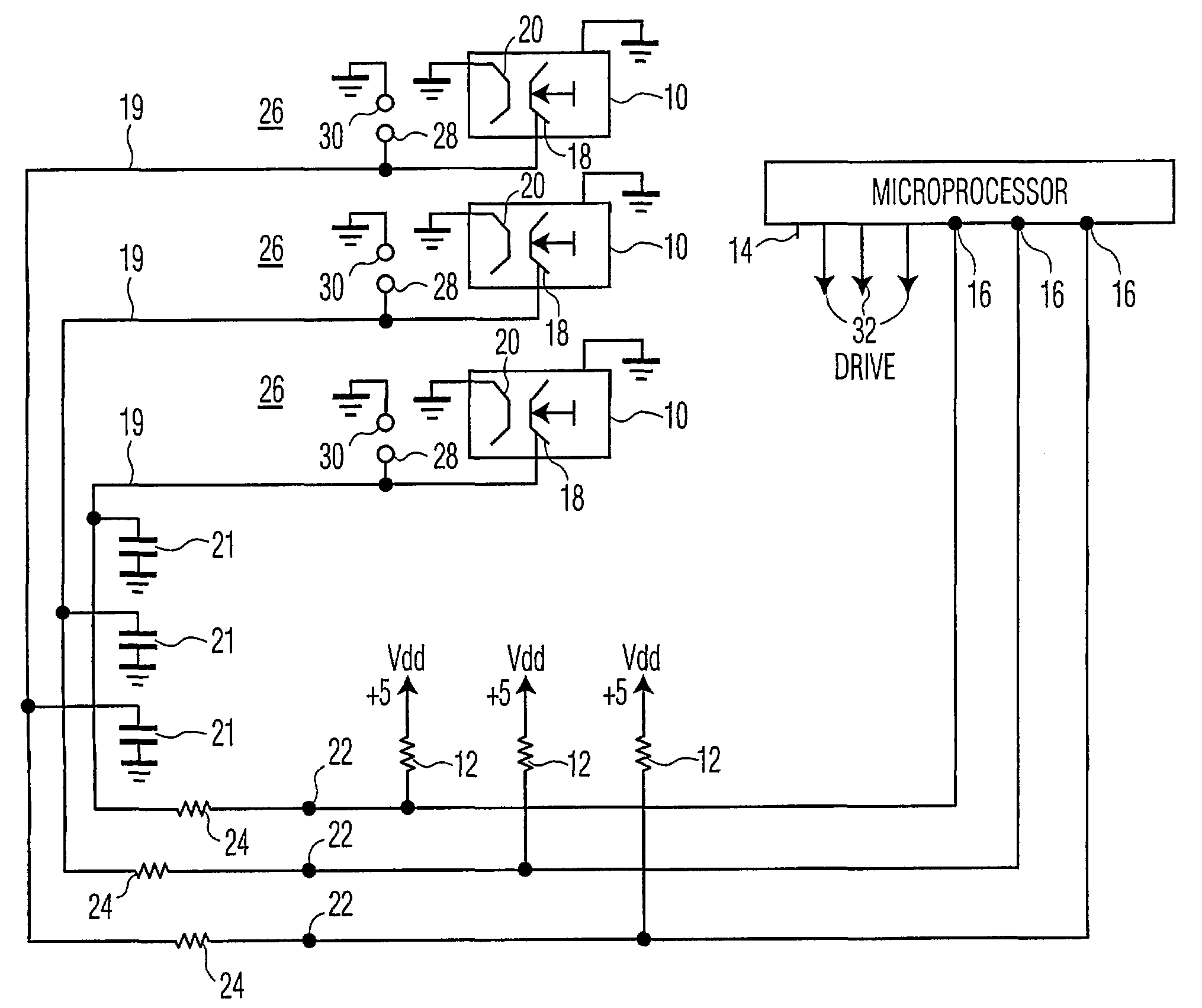
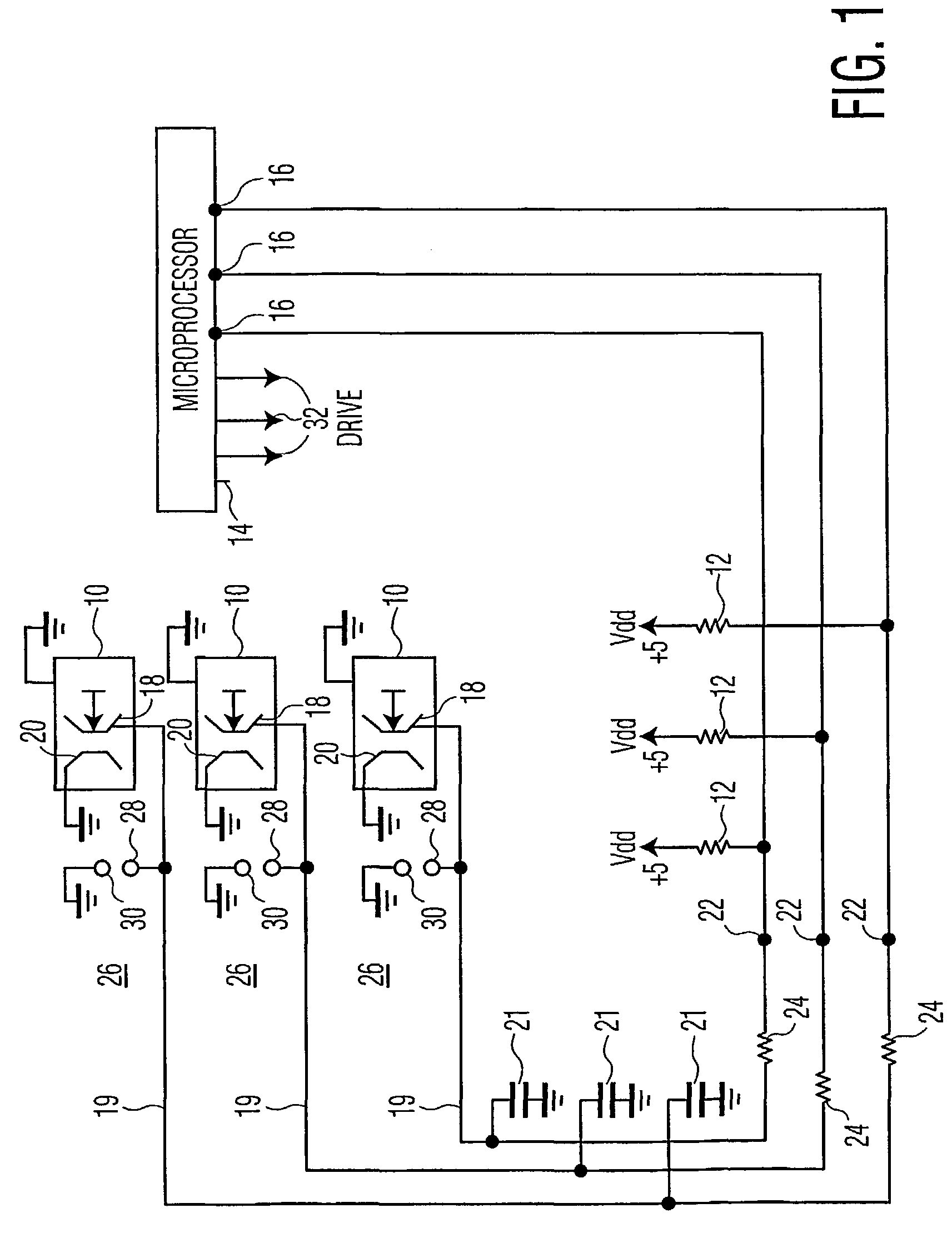
[0011]Referring now to FIG. 1, there is shown a schematic of representative pertinent portions of keyboard switches 10 with respective pull-up resistors 12, and a programmable microprocessor 14 having appropriate ROM, RAM and CPU (not shown), with programmable input / output (I / O) terminals 16 coupled to respective switches 10. The microprocessor of the exemplary embodiment is an ST92196 manufactured by STMicroelectronics Co. and, as is common for such microprocessors, can be programmed for individual I / O terminals 16 to be, inter alia, input terminals or output terminals, in a high or low state. A two hundred page data sheet is available from the manufacturer, to enable those skilled in the art, to circuit design with and program the microprocessor.

[0012]Switches 10 include a printed circuit trace and respective movable contact 18 which is movable into electrical contact with a grounded stationary contact and respective printed circuit trace 20 when a key of a keyboard or keypad (no...


PUM


Abstract

An apparatus and method therefor wherein instead of applying a high bias voltage 100 per cent of the time to leads susceptible to dendrite formation, the bias voltage is switched from a low bias voltage to a high voltage bias mode when the leads (19) are to be read or scanned by a microprocessor (14), and the bias voltage is then switched back to a low bias voltage mode when the lines are not being read, e.g., at other times, thereby greatly reducing the high bias “on” time and dramatically reducing the probability of dendrite formation. The reduction of high bias voltage “on” time is accomplished by programming the microprocessor (14) to switch the applicable input ports (16) to be output ports when the leads (19) are not to be read. As output ports, the output impedance and output voltage of the microprocessor are low as opposed to a high input impedance when the terminals are input terminals. When the leads are configured as output leads, the voltage division of the microprocessor low output impedance, in combination with a large valued pull-up resistor (12) which provides the high bias voltage when the leads are input leads, makes the voltage bias on the leads low, thus greatly reducing the probability of dendrite formation.

Description

[0001]This application claims the benefit under 35 U.S.C. § 365 of International Application PCT / US01 / 16953, filed May. 24, 2001, which was published in accordance with PCT Article 21(2) on Dec. 13, 2001 in English; and which claims benefit of U.S. Provisional Application Ser. No. 60 / 208,750 filed Jun. 2, 2000.BACKGROUND[0002]Dendrites, also known as whiskers, are microscopic crystalline metallic filaments that grow outwardly in various directions from solder, copper and other similarly susceptible metals. The dendrites have the appearance of very fine hairs which can bridge adjacent parts or conductors, e.g., on a printed circuit board surface between two traces, or between two solder joints, which in both cases have a voltage potential between them. The dendrite formation caused by these metallic dendritic bridges develops over a period of time and may eventually extend between the printed circuit board traces, particularly if the traces are close to each other and / or are unplated...

Claims


Application Information

Patent Timeline
IPC IPC(8): G06F3/00G06F15/78G06F3/02H03K19/003H03K19/173H03M11/02H03M11/20H05K1/02H05K1/18H05K3/34
CPCG06F3/0202H03K19/003H03K19/1731H03M11/02H03M11/20H05K1/0256H05K1/0262H05K1/181H05K3/3421H05K2201/0769H05K2201/10212H05K2201/10689Y02P70/50H03K19/00
Inventor TESTIN, WILLIAM JOHNKING, DALE WAYNE
Owner MAGNOLIA LICENSING LLC
Why Eureka
Try Eureka