Ankle replacement system

a technology for replacing prostheses and joints, applied in the field of implants and systems, can solve the problems of limited use and additional stress on the knee and hip joints, and achieve the effect of improving long-term results

Active Publication Date: 2009-05-19
INBONE TECH
View PDF5 Cites 102 Cited by
  • Summary
  • Abstract
  • Description
  • Claims
  • Application Information

AI Technical Summary

Benefits of technology

[0008]Another aspect of the invention provides articulating artificial joint surfaces comprising complementary ball-and-socket surfaces that not only articulate, but also allow the artificial joint to rotate about an axis. This makes possible more uniform wear of the surfaces to maximize function and longevity of the prostheses.
[0013]Another aspect of the invention provides an ankle replacement system that can be installed using minimally invasive intramedullary guidance established with respect to the major axis of the tibia by minimally invasive access through the calcaneus, through an incision in the bottom of the foot. Intramedullary guidance along the axis of the tibia makes it possible to make properly oriented bony cuts of the talus and tibia through anterior access to the ankle joint. Proper overall alignment of the total ankle system is achieved in desired alignment and orientation with all the natural axes of the native ankle joint it replaces, and improved long term results are achieved.

Problems solved by technology

Fusion, however, rendered the ankle stiff and generally immobile relative to the lower leg, resulting in limited use and additional stresses on the knee and hip joints.

Method used


Image

  • Ankle replacement system
  • Ankle replacement system
  • Ankle replacement system

Examples


Embodiment Construction

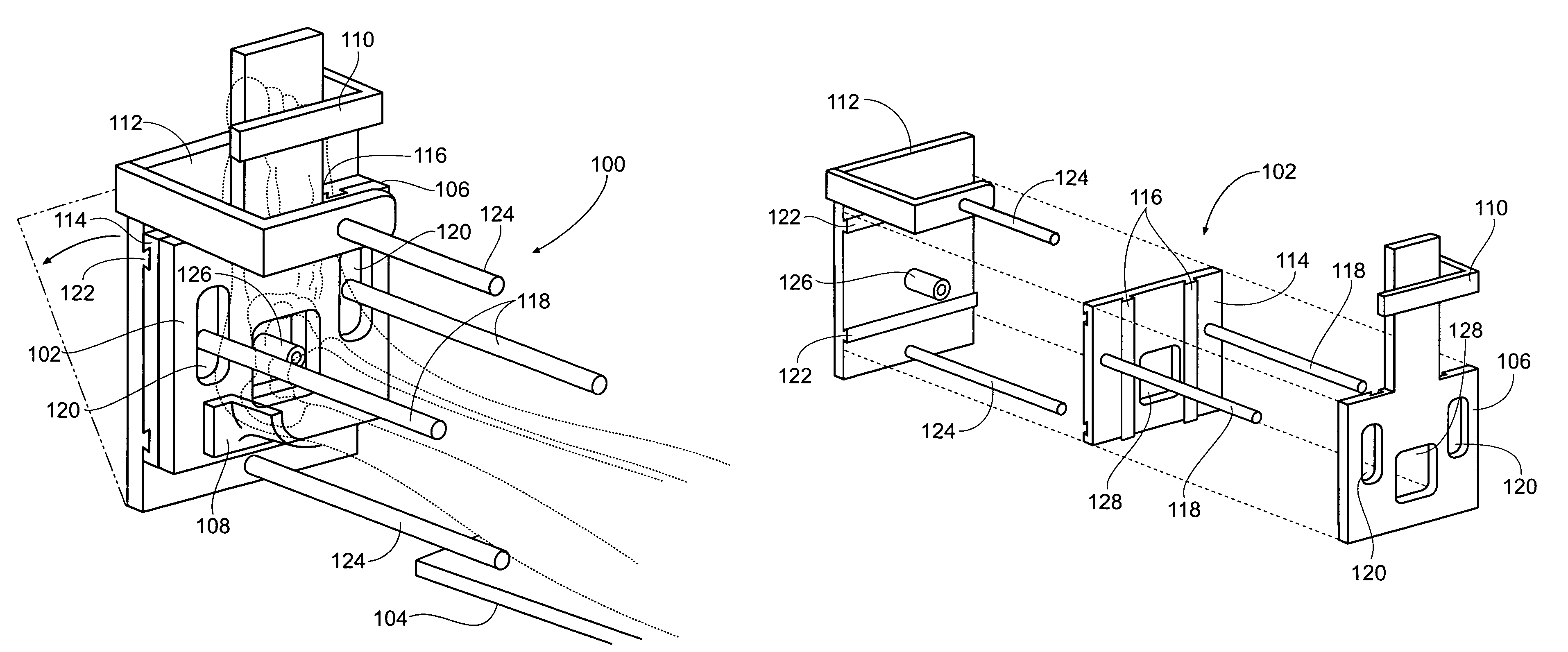
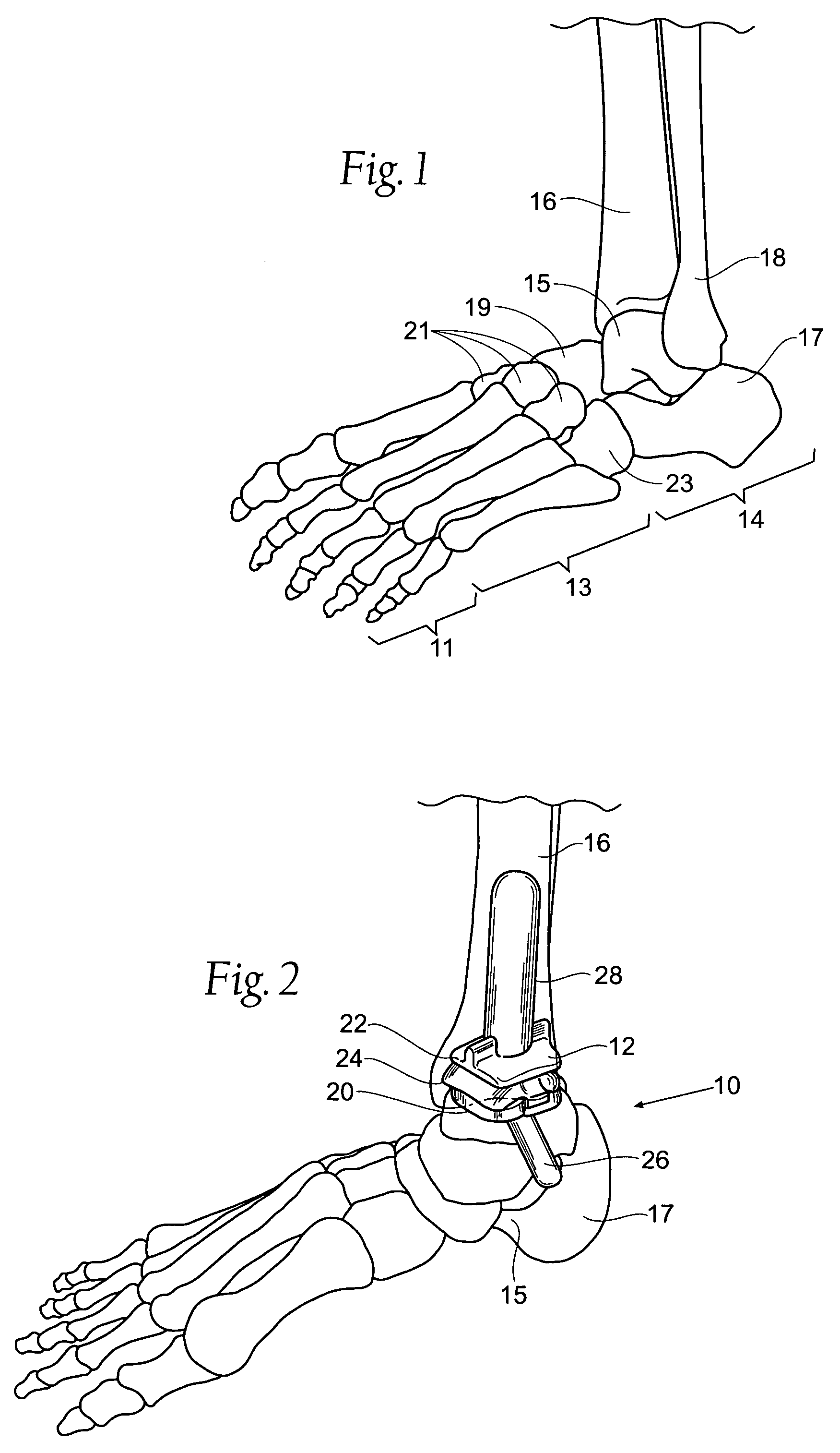
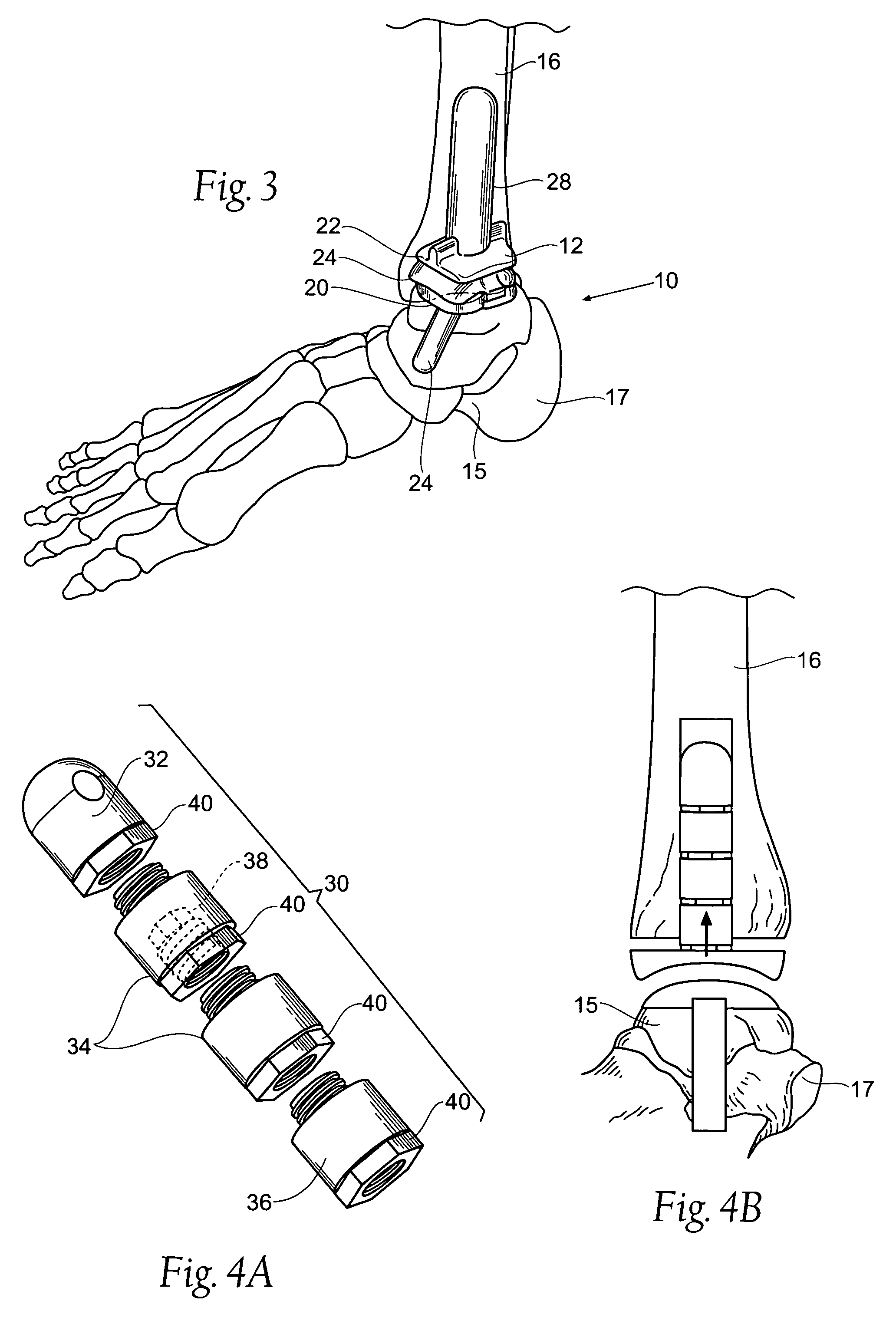
[0058]This description is divided into logical sections for ease of disclosure. Section I introduces the reader to the anatomy of the lower leg and ankle, to set the anatomic backdrop of the total ankle replacement systems and methods that will be described. Section II provides structural descriptions of representative embodiments of the tibial and talar-calcaneal components of total ankle replacement systems and devices that have the desired form, fit, and function. Section III provides descriptions of representative embodiments of systems, methods, and techniques useful for the implantation of total ankle replacement systems and devices to achieve their desired form, fit, and function.

[0059]Although the disclosure hereof is detailed and exact to enable those skilled in the art to practice the invention, the physical embodiments herein disclosed merely exemplify the invention, which may be embodied in other specific structure. While the preferred embodiment has been described, the ...


PUM

PropertyMeasurementUnit
widthsaaaaaaaaaa
lengthsaaaaaaaaaa
lengthaaaaaaaaaa

Abstract

A prosthesis suited for orthopedic implantation possesses a multi-piece stem component that supports an artificial joint surface that can articulate with another artificial joint surface in various ways. The prosthesis can be assembled in a snap fit and / or interlocking fashion that provides positive locking means without the use of screws or other fasteners. The prosthesis can accommodate fitment of a plastic joint surface made, e.g., from ultra high molecular weight polyethylene. The prosthesis is well suited for use in an ankle replacement system that can be installed using minimally invasive intramedullary guidance established with respect to the major axis of the tibia by minimally invasive access through the calcaneus, through an incision in the bottom of the foot. The prosthesis makes possible the installation of a total ankle system using minimally invasive anterior access to the ankle joint for making bony cuts and to install prosthesis components.

Description

RELATED APPLICATION[0001]This application claims the benefit under 35 U.S.C. § 119(e) of U.S. Provisional Patent Application Ser. No. 60 / 661,584, filed Mar. 14, 2005, and entitled “Ankle Replacement System.”FIELD OF THE INVENTION[0002]The invention relates to ankle replacement prostheses and systems, as well as associated surgical instruments and procedures.BACKGROUND OF THE INVENTION[0003]Until the early to mid 1970's, patients with injured or diseased ankle joints commonly resulting from rheumatism, or degenerative or traumatic arthritis, had few options when their ankle joints failed. The most common procedure to help these patients regain some use of their ankle was obliteration of the joint by fusion, a procedure that is still commonly used today. Fusion, however, rendered the ankle stiff and generally immobile relative to the lower leg, resulting in limited use and additional stresses on the knee and hip joints.[0004]Probably the first reported use of total ankle prosthesis wa...

Claims


Application Information

Patent Timeline
Patent Type & Authority Patents(United States)
IPC IPC(8): A61B17/58
CPCA61B17/15A61F2/4202A61F2/4606A61B17/8875A61B2019/5238A61F2002/30301A61F2002/30332A61F2002/30383A61F2002/30405A61F2002/30492A61F2002/305A61F2002/30507A61F2002/3055A61F2002/30551A61F2002/30604A61F2002/30649A61F2002/3069A61F2002/30884A61F2002/4205A61F2002/4207A61F2002/4631A61F2220/0025A61F2220/0033A61F2230/0095A61F2310/00017A61F2310/00023A61F2310/00029A61F2310/00131A61F2310/00179A61F2310/00329A61F2310/00796A61F2310/0097A61B2017/1775A61F2002/4627A61B2090/376A61B17/1775A61F2310/00359A61F2/30771A61F2002/30935
Inventor REILEY, MARK A.GREENBERG, LOUISMAULDIN, R. GARRET
Owner INBONE TECH
Why Eureka
Try Eureka