Class-E radio frequency power amplifier with feedback control

a technology of radio frequency power amplifier and feedback control, which is applied in the direction of dc amplifiers with modulator-demodulator, amplifiers with semiconductor devices/discharge tubes, dc amplifiers with modulators, etc., can solve the problems of class-e amplifiers not reaching anywhere near the theoretical limits, amplifiers are not very efficient, and dissipate a significant amount of energy

Inactive Publication Date: 2009-05-19
KENERGY INC
View PDF17 Cites 27 Cited by
  • Summary
  • Abstract
  • Description
  • Claims
  • Application Information

AI Technical Summary

Problems solved by technology

Unfortunately, these amplifiers are not very efficient and dissipate a significant amount of energy.
However, in practice, Class-E amplifiers do not achieve anywhere close to the theoretical limits.
With this technique, it is impossible to control the range of the power depending on the need.

Method used


Image

  • Class-E radio frequency power amplifier with feedback control
  • Class-E radio frequency power amplifier with feedback control
  • Class-E radio frequency power amplifier with feedback control

Examples


Embodiment Construction

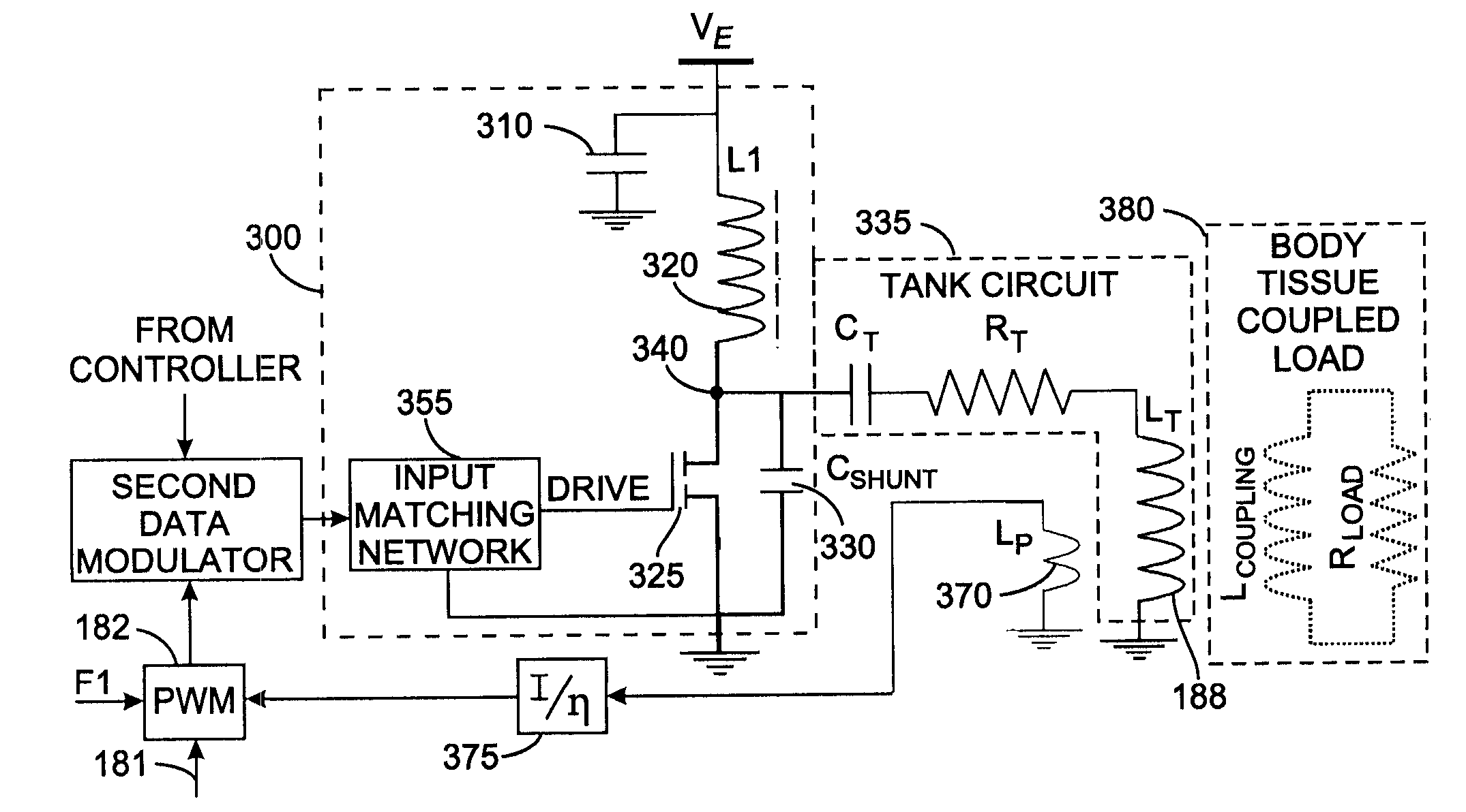
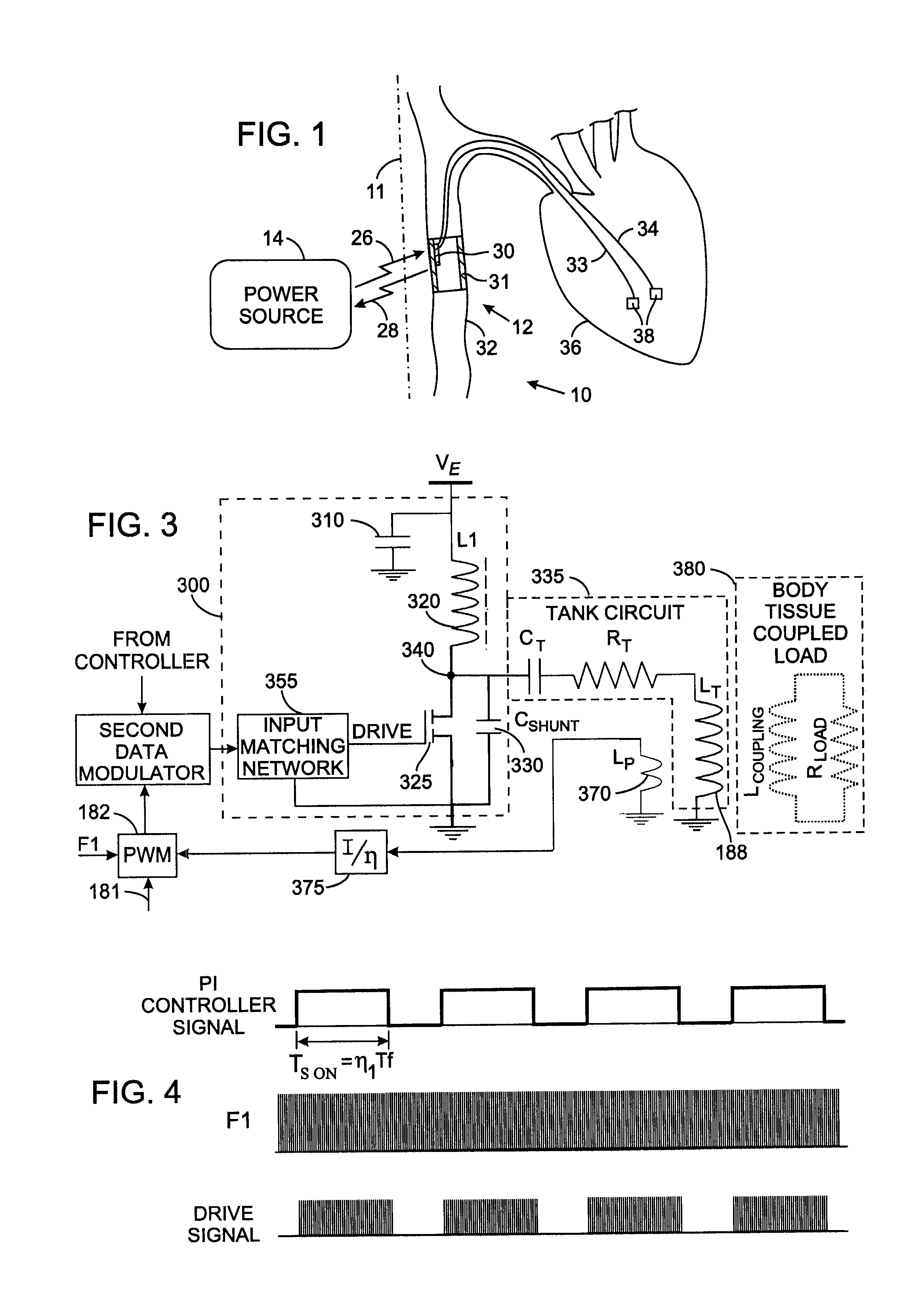
[0018]Although the present Class-E power amplifier with feedback control is described with respect to an intravascular implanted device, it should be understood that the power amplifier is applicable for a number of medical and non-medical applications. Such other applications include, but are not limited to, medical imaging power amplifiers, such as are used for MRI radio frequency power amplification, implants (e.g. intravascular amplifiers, cochlear), high voltage amplifiers and in general, wherever a highly efficient, practical signal power amplification is required with a feedback control.

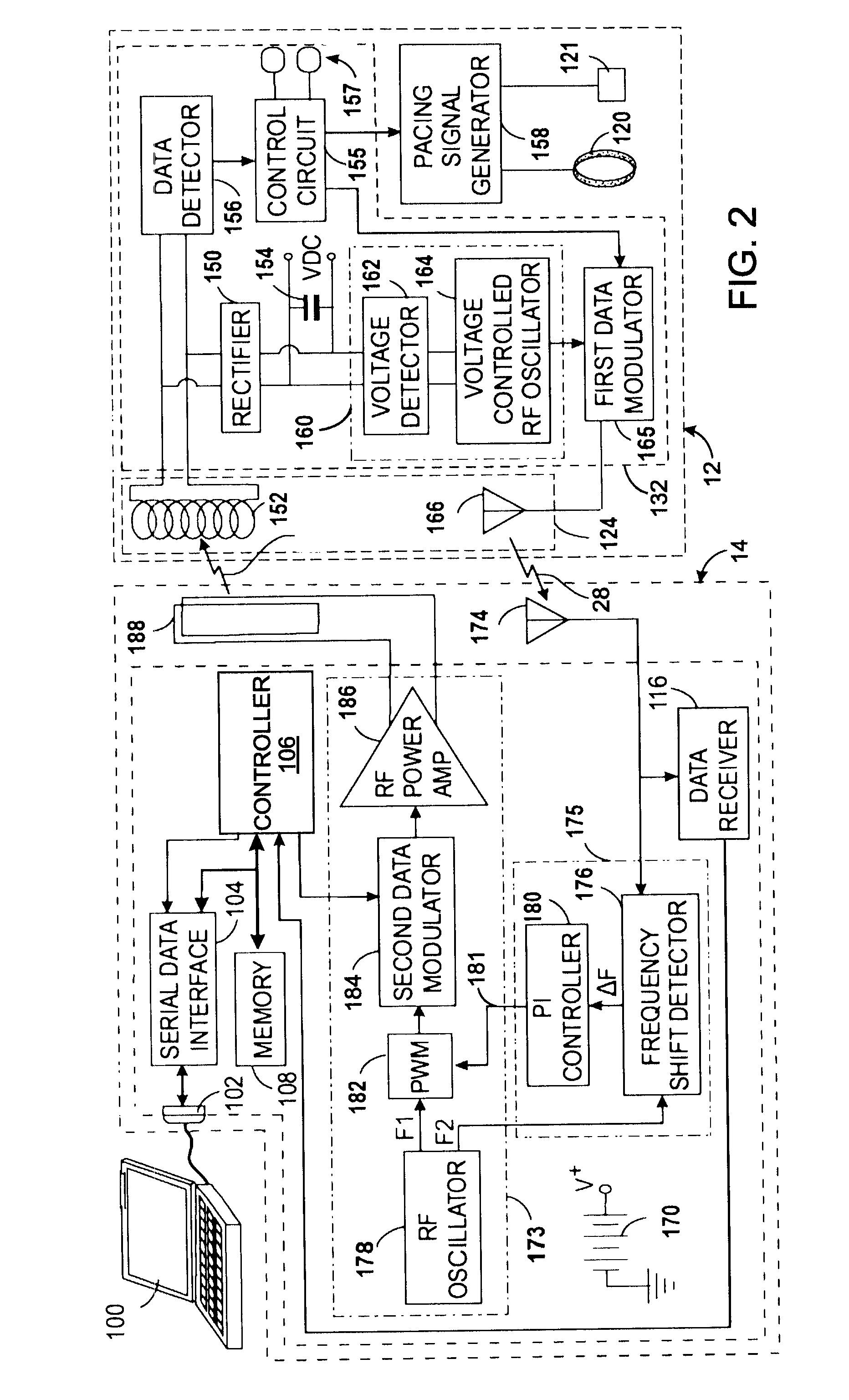
[0019]With initial reference to FIG. 1, a wireless transvascular platform 10 for tissue stimulation includes an extracorporeal power source 14 and a medical device 12 implanted inside the body 11 of an animal. The extracorporeal power source 14 includes a battery that powers a transmitter that sends a first radio frequency (RF) signal 26 to the medical device 12. The medical device 12 derives ...


PUM


Abstract

A Class-E power amplifier includes a choke and a switch connected in series between a source of a supply voltage and circuit ground and connected to an inductively coupled coil. An output node of the amplifier is formed between choke and the switch and connected to a transmitter antenna. A shunt capacitor couples the amplifier's output node to the circuit ground. A feedback signal, indicating an intensity if the signal at the amplifier output node is used to vary the input signal to the Class-E power amplifier and thereby control operation of the switch.

Description

CROSS-REFERENCE TO RELATED APPLICATIONS[0001]This application claims benefit of U.S. Provisional Patent Application No. 60 / 776,853 filed Feb. 24, 2006.STATEMENT REGARDING FEDERALLY SPONSORED RESEARCH OR DEVELOPMENT[0002]Not ApplicableBACKGROUND OF THE INVENTION[0003]1. Field of the Invention[0004]The present invention relates to radio frequency power amplifiers, and more particularly to a radio frequency Class-E power amplifier with feedback control.[0005]2. Description of the Related Art[0006]A remedy for a patient with a physiological ailment is to implant an electrical stimulation device that provides provide therapy to the patient. An electrical stimulation device is a small electronic apparatus that stimulates an organ or part of an organ with electrical pulses. It includes a pulse generator, implanted in the patient, and from which electrical leads extend to electrodes placed adjacent to specific regions of the organ.[0007]An improved apparatus for physiological stimulation of...

Claims


Application Information

Patent Timeline
Patent Type & Authority Patents(United States)
IPC IPC(8): H03F3/38
CPCA61N1/3787H03F1/34H03F3/217H03F3/2176H03F2200/351
Inventor BULKES, CHERIKDENKER, STEPHENBEUTLER, ARTHUR J.
Owner KENERGY INC
Why Eureka
Try Eureka