Tilt control method and optical disc apparatus

a control method and optical disc technology, applied in the direction of digital signal error detection/correction, instruments, recording signal processing, etc., can solve the problems of inability to appropriately inability to obtain the desired linear characteristic, and inability to properly detect the amount of light returning from the sil. achieve the effect of reducing tilting and high-quality recording and playback signals

Inactive Publication Date: 2009-05-19
SONY CORP
View PDF25 Cites 15 Cited by
  • Summary
  • Abstract
  • Description
  • Claims
  • Application Information

AI Technical Summary

Benefits of technology

[0009]The present invention has been conceived in view of the afore mentioned situation and it is advantageous to provide a tilt control method and optical disc apparatus capable of performing control in such a manner that tilting is eliminated so as to enable an appropriate gap servo operation to be carried out.
[0023]As shown above, according to the preferred embodiments of the present invention, it may be possible to make tilt substantially zero, and it may be possible to carry out an appropriate gap servo operation. It is therefore possible to achieve high-quality recording and playback signals as a result of the tilt being substantially zero.

Problems solved by technology

Even if a small tilt occurs, the SIL may collide with the disc, making arrangement of an end surface of an SIL in a near field difficult.
In particular, it is not possible to appropriately detect an amount of light returning from an SIL as a result of tilting occurring.
Namely, when tilting is present, the amount of returning light does not become zero even when the SIL makes contact with the disc, and it is not possible to obtain the desired linear characteristic for between the cap and the amount of returning light necessary for the gap servo operation.
This constitutes an obstacle to the gap servo operation.
Further, in the event that the tilt is not approximately zero, a coma aberration may occur at the time of recording or reproducing a signal and quality of recording and playback is compromised.

Method used


Image

  • Tilt control method and optical disc apparatus
  • Tilt control method and optical disc apparatus
  • Tilt control method and optical disc apparatus

Examples


Embodiment Construction

[0045]The following is a description based on the drawings of preferred embodiments of the present invention.

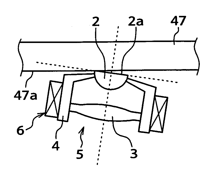
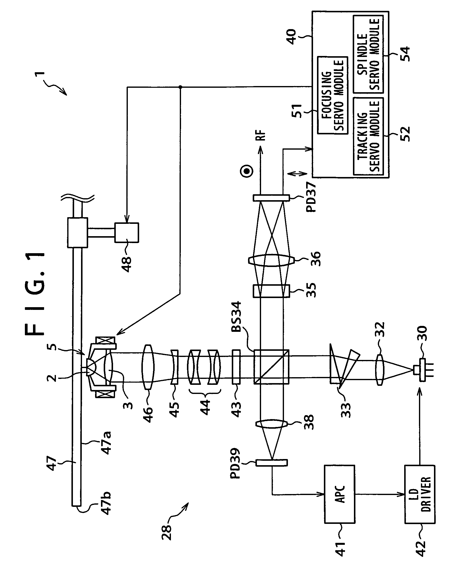
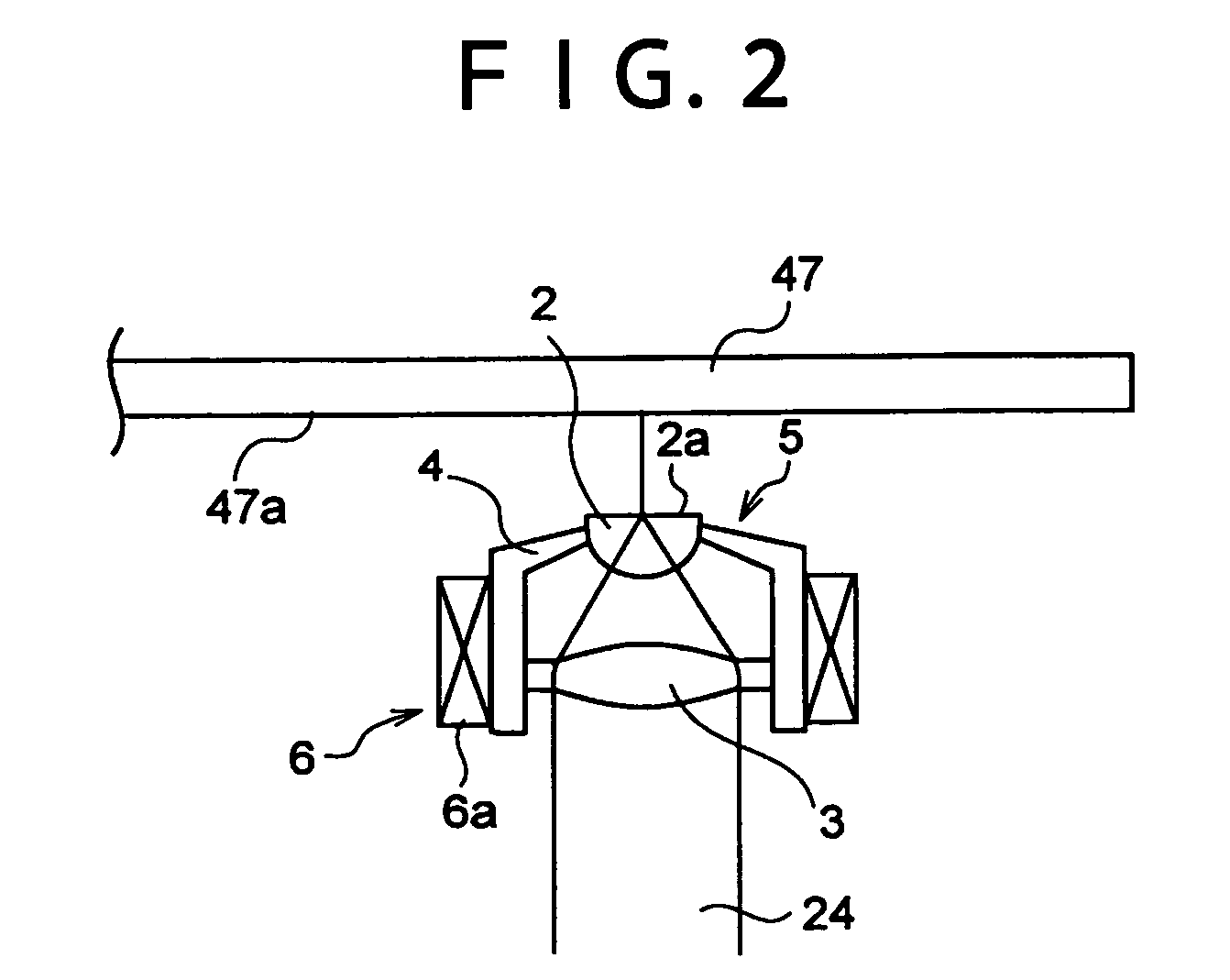
[0046]FIG. 1 is a view showing a configuration for an optical disc for a first embodiment of the present invention. An optical disc apparatus 1 is included of an optical head 28, servo control system 40 and spindle motor 48. The optical head 28 includes a laser diode (LD) 30 constituting a light source, collimator lenses 32 and 46, an anamorphic prism 33 for shaping laser light, a beam splitter (BS) 34, a quarter wavelength plate (QWP) 43, a chromatic aberration correction lens 44, a laser beam expanding lens 45, a Wollaston prism 35, light gathering lenses 36 and 38, a light gathering element 5, photodetectors (PDs) 37 and 39, an automatic power controller 41, and an LD driver 42.

[0047]The Wollaston prism 35 is composed of two prisms. Light incident on the Wollaston prism 35 goes out as two straight lines of polarized light that are mutually orthogonal. A PD 37 outputs an RP...


PUM

PropertyMeasurementUnit
wavelengthaaaaaaaaaa
distanceaaaaaaaaaa
gap lengthaaaaaaaaaa

Abstract

According to a preferred embodiment of the present invention, in order to provide a tilt control method and optical disc apparatus capable of exerting control to eliminate tilt and capable of carrying out an appropriate gap servo operation, a light gathering element positioned facing a disc recordable with a signal, and capable of gathering light irradiated from a light source as near-field light at a position where a distance to the disc constitutes a first distance is made to come into contact with the disc (step 2), and tilt is controlled with the light gathering element in contact with the disc (steps 3 to 7). As a result, tilting with respect to the disc is adjusted with the SIL in contact with the disc, tilting can be eliminated in a reliable manner, and a gap servo operation can be carried out in an appropriate manner.

Description

CROSS REFERENCE TO RELATED APPLICATONS[0001]The present document is based on Japanese Priority Documents JP2004-035814 and JP2004-292426, filed to the Japanese Patent Office on Feb. 12, 2004 and Oct. 5, 2004 respectively, the contents of which being incorporated herein by reference.BACKGROUND OF THE INVENTION[0002]1. Field of the Invention[0003]The present invention relates to a tilt control method and optical disc apparatus applying near-field light to perform at least one of recording and playing back of a signal.[0004]2. Description of Related Art[0005]In the related art, optical disc apparatuses applying laser light in order to increase recording density on an optical disc are proposed for recording or playing back (reproducing) signals using near-field light. With optical disc apparatuses employing near-field light, it is necessary to (gap servo) control a gap between disc and an end surface of an object lens etc., such as an SIL (Solid Immersion Lens) arranged in an optical he...

Claims


Application Information

Patent Timeline
Patent Type & Authority Patents(United States)
IPC IPC(8): G11B5/58G11B7/00G11B7/095G11B7/08G11B7/135G11B7/1372G11B7/1387
CPCG11B7/0956G11B7/1387G11B2007/13727
Inventor ISHIMOTO, TSUTOMUSAITO, KIMIHIRO
Owner SONY CORP
Why Eureka
Try Eureka