Method and apparatus for forming sheet metal

a sheet metal and method technology, applied in the direction of metal-working feeding devices, manufacturing tools, positioning devices, etc., can solve the problems of inability to observe the requirement by using the conventional forming technique, difficulty in providing a sufficient amount of commercialized products, and significant reduction of sheet thickness, etc., to achieve the effect of high accuracy and short tim

Inactive Publication Date: 2009-05-26
AMINO CORP (JP)
View PDF11 Cites 63 Cited by
  • Summary
  • Abstract
  • Description
  • Claims
  • Application Information

AI Technical Summary

Benefits of technology

[0015]The present invention is contrived to solve the aforementioned problems, and an object of the present invention is to provide a forming method capable of forming a three-dimensional product such as a prototype for commercialized press-forming in short time and with high accuracy, without limitations as to the shape or generating body wrinkles caused by a redundant material.
[0018]According to the method of forming a sheet metal according to the present invention, the drawing-forming by the forming punch and the incremental forming by the shaping tool are combined. Therefore, it is possible to minimize reduction of the sheet thickness and form a vertical wall having a forming angel of 15° to 25°. In addition, it is possible to provide sufficient hardness even for a tool trace and reduce time for forming.
[0019]Furthermore, the drawing-forming and the incremental forming are combined to sequentially perform forming in a stepping manner such that the forming punch is maintained in a position to once lock movement of a material after the drawing-forming is performed by raising the forming punch to a predetermined height, the incremental forming is performed in this state, the clamp pressure is reduced, the drawing-forming is performed again to a desired height by raising the forming punch, and the incremental forming is performed by once locking movement of a material in this state. As a result, it is possible to prevent body wrinkles caused by a redundant material. Therefore, it is possible to perform forming with high accuracy even in any complicated shapes.
[0021]According to the apparatus of forming a sheet metal of the present invention, it is possible to implement all of the effects of the method of forming a sheet metal according to the present invention.
[0024]According to the present invention, the forming is performed in one place until a final product or a product having a shape near the final is obtained. Therefore, it is possible to improve efficiency.
[0026]Therefore, it is possible to manufacture a product having a recessive top portion with high accuracy.

Problems solved by technology

Therefore, it is difficult to provide a sufficient amount of commercialized products, such as 500 pieces per a month.2) A sheet thickness is significantly reduced.
However, this requirement cannot be observed by using the conventional forming technique.3) It is difficult or impossible to form a vertical wall.
If there is an abrupt angle change in the formed product, it is difficult to perform forming to model this shape.
Therefore, in addition to 2), there is a limitation to the shape that can be formed.4) The surface finishing is not good.
If a pitch is made minute to reduce this tool trace, the forming process takes longer time.5) Accuracy is insufficient.
Therefore, the finished product may be poor in sheet thickness reduction or numerical accuracy in comparison with a press-formed product.
As a result, product accuracy may be degraded.

Method used


Image

  • Method and apparatus for forming sheet metal
  • Method and apparatus for forming sheet metal
  • Method and apparatus for forming sheet metal

Examples


Embodiment Construction

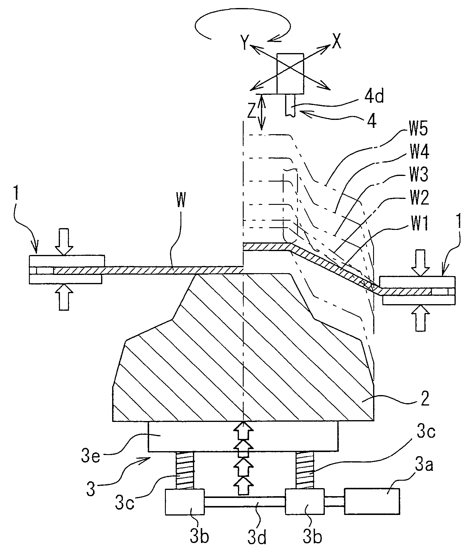
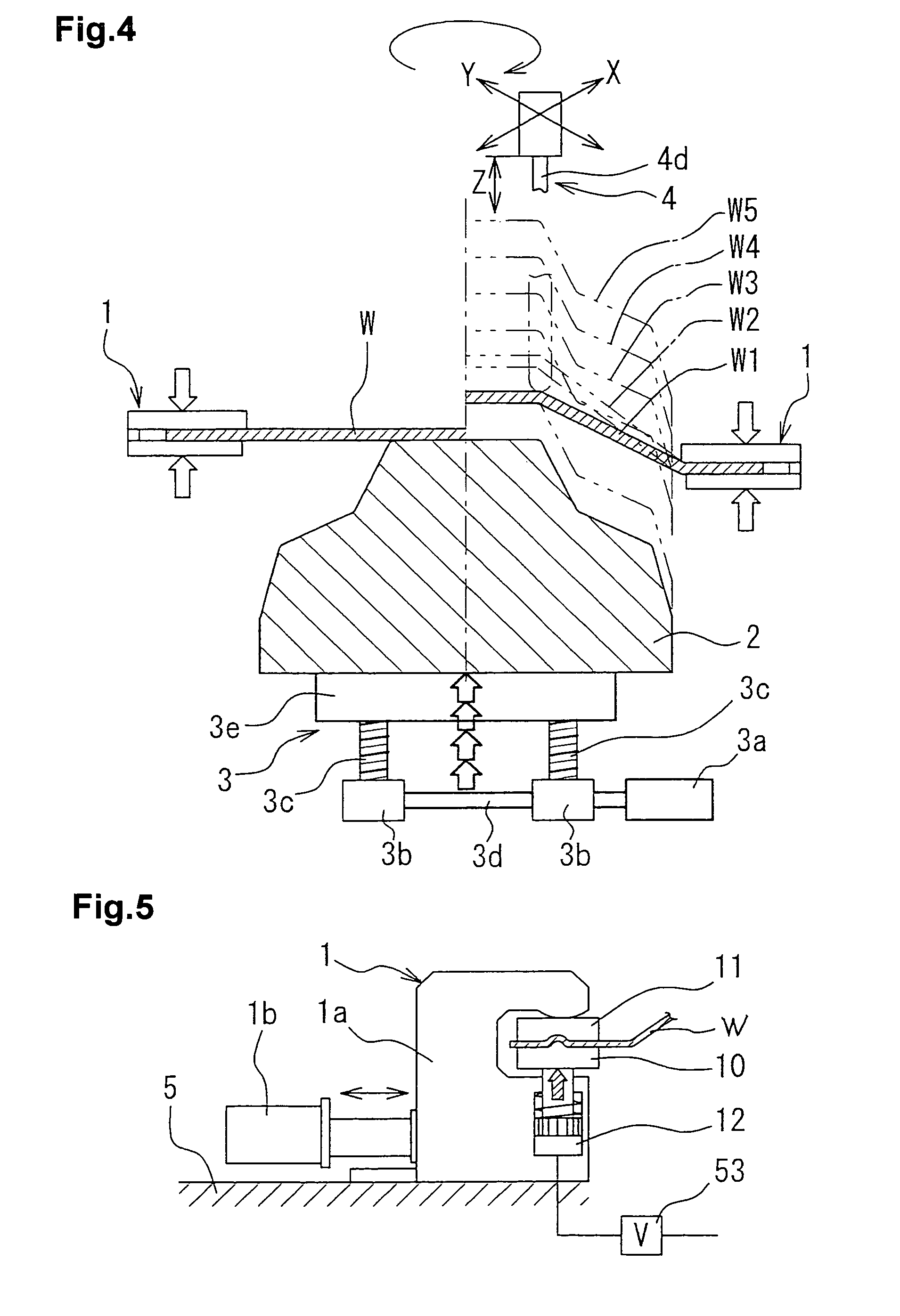
[0040]Hereinafter, embodiments of the present invention will be described with reference to the accompanying drawings. FIGS. 4 to 7 show an example of a method and apparatus for forming a sheet metal according to the present invention.

[0041]In FIG. 4, the reference numeral 1 denotes a plurality of clamp fixtures arranged in a required interval on a bed 5 for clamping edges of a blank workpiece (a sheet type) W in a sheet thickness direction. The clamp fixture 1 has a variable clamp pressure and is capable of moving in a forward / backward direction or stopping in a desired position. The reference numeral 2 denotes a forming punch having a desired shape disposed in an inward direction from the clamp fixture. The reference numeral 3 denotes a computerized numerical controlled (CNC) forming punch elevator which stepwise raises the forming punch 2 to be pushed into the blank workpiece W and sequentially stops at setup positions for the drawing-forming.

[0042]The reference numeral 4 denotes...


PUM

PropertyMeasurementUnit
thicknessaaaaaaaaaa
forming angleaaaaaaaaaa

Abstract

In order to provide a method and apparatus for forming a sheet metal, in which a three-dimensional product such as a prototype for commercialized press-forming can be formed in short time without limitations as to the shape and with high accuracy, preventing body wrinkles or reduction of the sheet thickness,a process of: performing drawing-forming to a predetermine height by pushing the forming punch having a desired shape in the sheet thickness direction with the edges of the blank workpiece being clamped; performing shape-forming with the shaping tool in the opposite side to the forming punch by increasing a clamping pressure to lock movement of a material with the forming punch being pushed; performing drawing-forming again by decreasing the clamping pressure and raising the forming punch by a desired height; and performing shape-forming with the shaping tool by increasing the clamping pressure to lock movement of a material, is repeated at least once.

Description

FIELD OF THE INVENTION[0001]The present invention relates to a method and apparatus for forming a sheet metal.BACKGROUND ART[0002]As a method or means for processing a sheet metal in a 3-dimensional shape, there has been known a forming method in which a metal sheet is fixed on an X-Y table and pressed down by a tool disposed in an upper position and movable in a Z-axis direction. In this case, the tool is moved to sequentially generate plastic deformation in the metal sheet. In an application of this method, a forming model may be adopted. FIG. 1 shows an outline of this forming method.[0003]However, the conventional technique has the following shortcomings because the entire shape to be formed is sequentially formed by drawing a contour line with a bar-like tool.[0004]1) The forming requires much time until the end of the work. Therefore, it is difficult to provide a sufficient amount of commercialized products, such as 500 pieces per a month.[0005]2) A sheet thickness is signific...

Claims


Application Information

Patent Timeline
Patent Type & Authority Patents(United States)
IPC IPC(8): B21D11/02B21D7/00
CPCB21D22/16B21D22/185B21D31/005B21D22/14B21D22/18
Inventor AMINO, HIROYUKIMATSUBARA, SHIGEOLU, YAN
Owner AMINO CORP (JP)
Why Eureka
Try Eureka