
Two-point control of a high-pressure pump for direct-injecting gasoline engines

a high-pressure pump and gasoline engine technology, which is applied in the direction of braking systems, process and machine control, instruments, etc., can solve the problem of airborne sound that is perceived as acoustic nois

Inactive Publication Date: 2009-05-26
AGFA INC +1
View PDF7 Cites 7 Cited by
  • Summary
  • Abstract
  • Description
  • Claims
  • Application Information

AI Technical Summary

Benefits of technology

The patent describes a method for operating an internal combustion engine equipped with a piston pump as a high-pressure pump. The high-pressure pump delivers fuel from a low-pressure region to a high-pressure side and a quantity control valve sets the quantity of fuel delivered. The high-pressure pump alternates between full delivery for individual or successive piston strokes and idle delivery for individual or successive piston strokes. The method limits the frequency of delivery by the high-pressure pump to the absolute amount required and reduces the acoustic emission of the control method. The two-point operation is activated when the engine speed falls below a minimum speed and / or when the injection quantity falls below a minimum quantity. The quantity control valve is opened when the upper pressure limit is reached and remains closed until the lower pressure limit is reached. The high-pressure pump can be operated in full delivery mode and in idle delivery mode in idle mode. The control unit and software described in the patent can execute the method.

Problems solved by technology

When in delivery mode, the high-pressure pump generates structure-borne acoustic vibrations, which generate airborne sound that is perceived as acoustic noise.

Method used


Image

  • Two-point control of a high-pressure pump for direct-injecting gasoline engines
  • Two-point control of a high-pressure pump for direct-injecting gasoline engines
  • Two-point control of a high-pressure pump for direct-injecting gasoline engines

Examples


Embodiment Construction

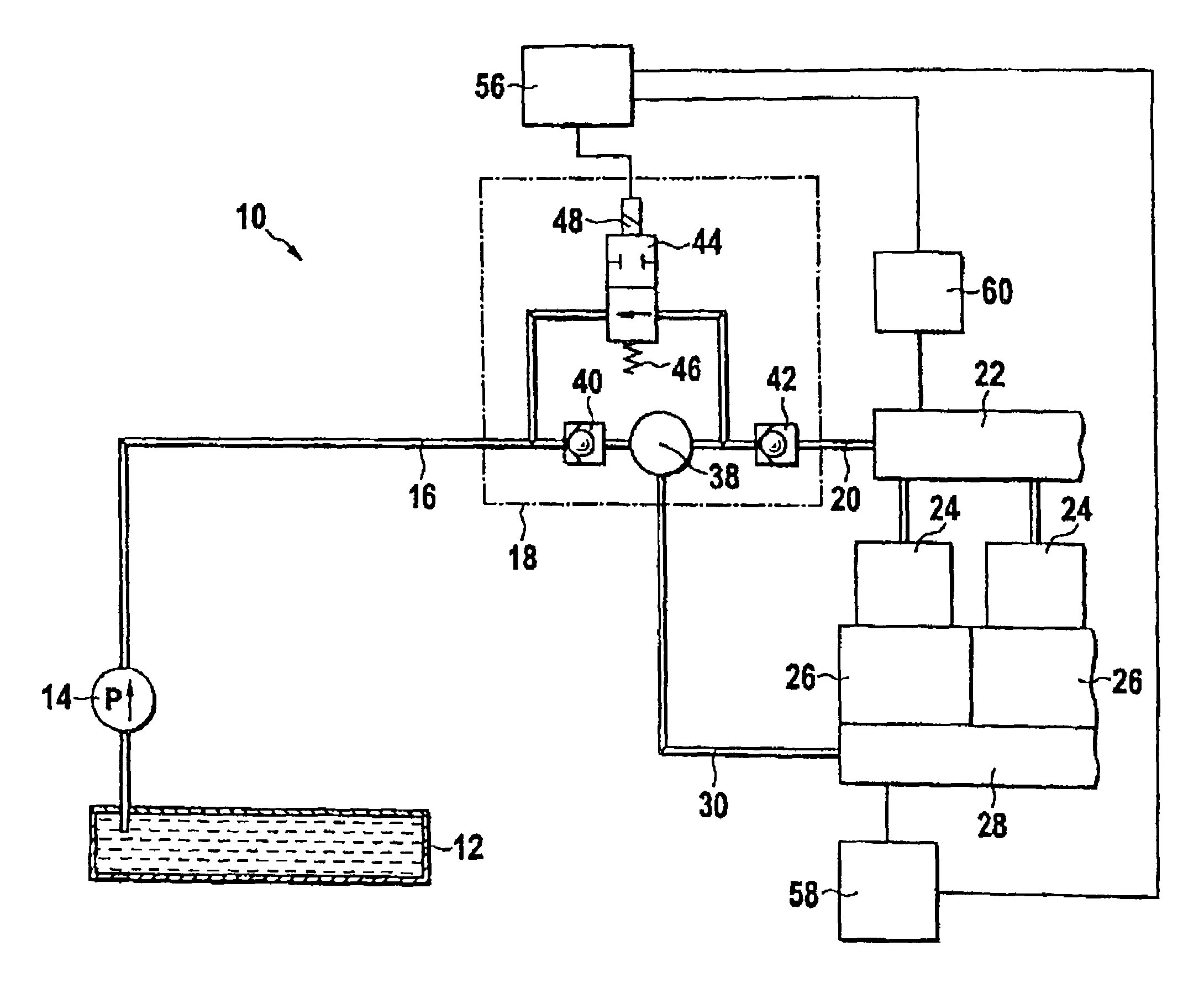
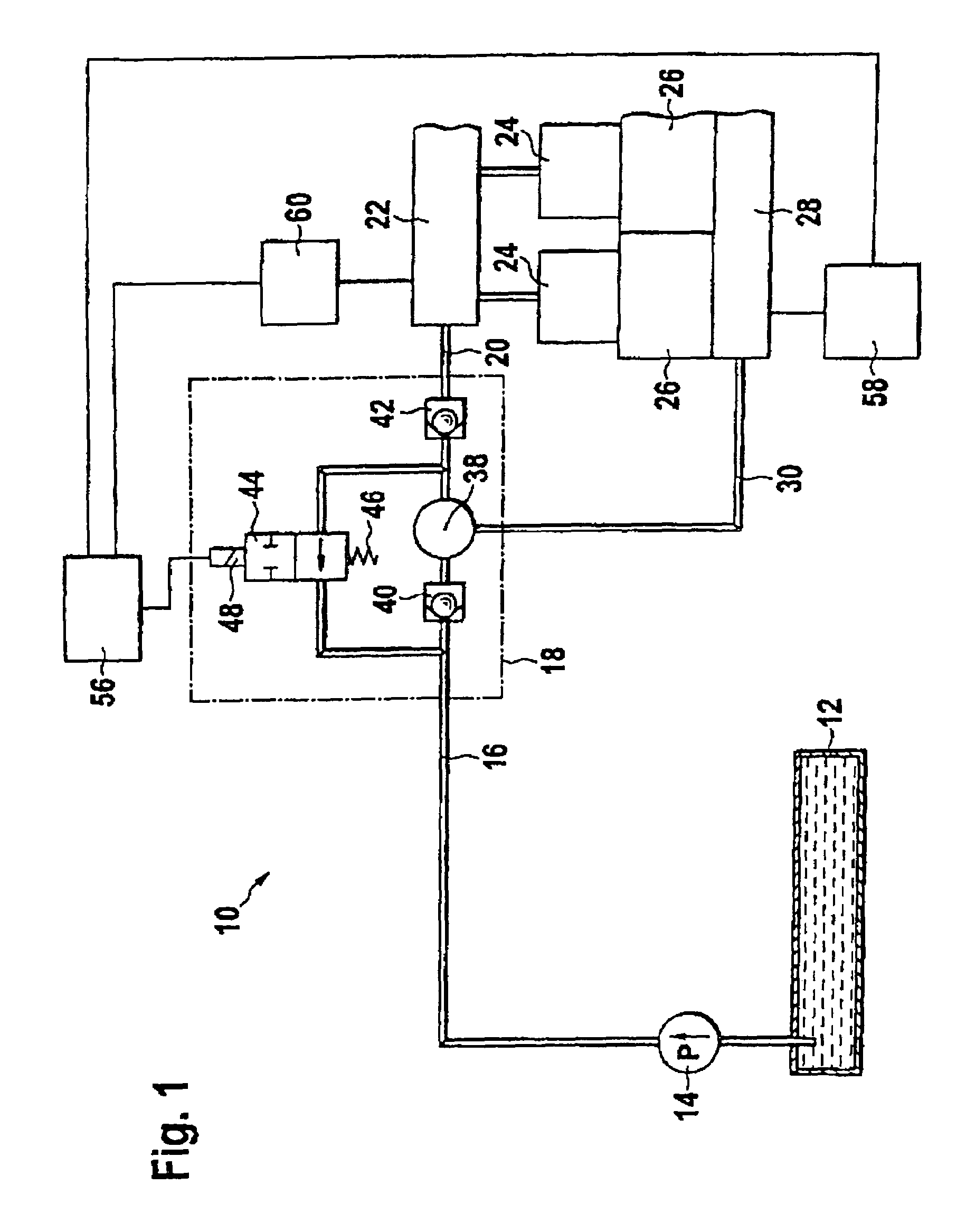
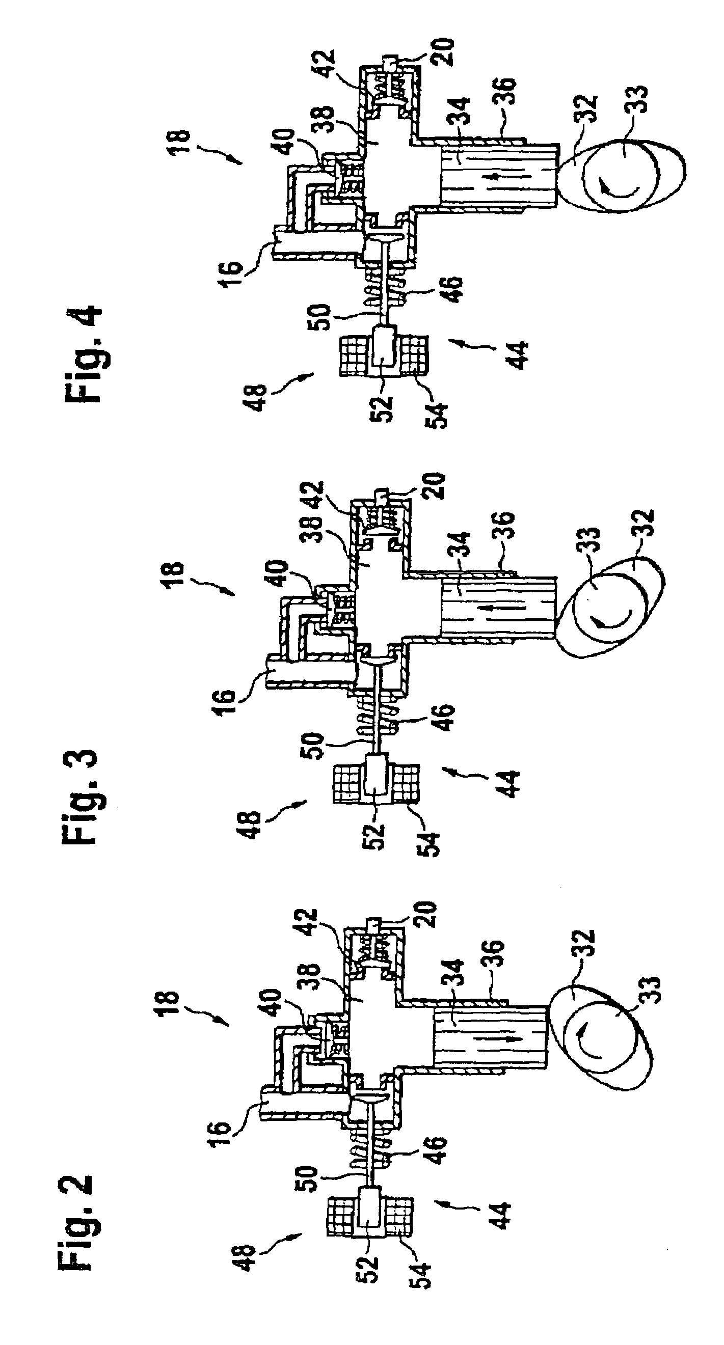
[0025]An internal combustion engine 10 according to FIG. 1—this can in particular be a direct-injecting gasoline engine—includes a fuel tank 12 from which an electrically driven prefeed pump 14 delivers fuel via a low-pressure line 16 to a high-pressure pump 18. The fuel travels onward via a high-pressure line 20 to an accumulator 22 (also referred to as the common rail) in which the fuel is stored at high pressure. The accumulator 22 has a number of injection devices 24 connected to it that inject the fuel directly into combustion chambers 26. The combustion of the fuel in the combustion chambers 26 sets a crankshaft 28 into rotation. Via a mechanical coupling 30 that is only depicted schematically in FIG. 1, the high-pressure pump 13 is driven by the crankshaft 28 serving as a drive shaft. The high-pressure pump 18 is a one-cylinder piston pump in which a drive cam 32 on a shaft 33 sets a piston 34 into a reciprocating motion. The piston 34 is guided in a housing 36 and delimits a...


PUM


Abstract

In a method for operating an internal combustion engine (10) equipped with a piston pump as a high-pressure pump (18), which is driven by a drive shaft (28) of the engine (10), in which the high-pressure pump (18) delivers fuel from a low-pressure region (16) to a high-pressure side (38) and a quantity control valve (44) sets the quantity of fuel delivered by the high-pressure pump (18), the acoustic emission of the high-pressure pump is reduced by virtue of the fact that the high-pressure pump (18) functions in a two-point operation, alternating between full delivery for individual or successive piston strokes and idle delivery for individual or successive piston strokes and, when the pressure falls below a lower pressure threshold, the full delivery is activated until an upper pressure threshold is reached.

Description

CROSS REFERENCE TO RELATED APPLICATIONS[0001]This application claims priority under 35 U.S.C. 119(a)-(d) to German Patent Application DE 102005014093.3, filed Mar. 29, 2005.BACKGROUND OF THE INVENTION[0002]1. Field of the Invention[0003]The present invention relates to a method for operating an internal combustion engine equipped with a piston pump as a high-pressure pump, which is driven by a drive shaft of the engine; the high-pressure pump delivers fuel from a low-pressure region to a high-pressure side and a quantity control valve sets the quantity of fuel delivered by the high-pressure pump.[0004]2. Related Art[0005]In direct-injection gasoline engines (GDI=gasoline direction injection), one-cylinder high-pressure pumps are used to raise the pressure from the preliminary pressure of the presupply pump (EFP=electric fuel pump) to the pressure required for the direct injection (50 to 200 bar). These one-cylinder pumps are operated with 2, 3, or 4 pump strokes per camshaft rotatio...

Claims


Application Information

Patent Timeline
Patent Type & Authority Patents(United States)
IPC IPC(8): F02M37/04
CPCF02M59/102F02M59/366F02M59/38F02M63/0225F02M63/024F02M59/10F02M59/36F02M63/02
Inventor KOEHLER, CHRISTIANSCHNELL, RUEDIGERHOLLMANN, TIMMLAMIRAND, YVES
Owner AGFA INC
Learn More