Linear actuator, and valve device and pump device using the same

a technology of actuator and valve body, which is applied in the direction of piston pump, positive displacement liquid engine, magnetic body, etc., can solve the problems of inability to obtain large thrust, reduced utilization efficiency of magnetic flux, and remarkably reduced thrust as volume decreases

Inactive Publication Date: 2009-05-26
SANKYO SEIKI MFG CO LTD
View PDF7 Cites 27 Cited by
  • Summary
  • Abstract
  • Description
  • Claims
  • Application Information

AI Technical Summary

Benefits of technology

[0014]In view of the problems described above, an embodiment may advantageously provide a linear actuator which is capable of obtaining a large thrust even when downsized and which is suitable for a mass production, and provide a valve device provided with this linear actuator.
[0015]Further, an embodiment may advantageously provide a small-sized pump device which is capable of performing a constant amount of discharge with a high degree of accuracy. Further, an embodiment may advantageously provide a small-sized pump device which is capable of performing a constant amount of discharge with a high degree of accuracy even when a diaphragm valve is used.
[0016]Further, an embodiment may advantageously provide a pump device which is provided with a plurality of outflow passages for discharging fluid and capable of accurately discharging an appropriate amount of fluid.

Problems solved by technology

However, this type of linear actuator has a problem that when its size is made smaller, its thrust remarkably decreases as its volume decreases.
Further, if only for a short time, the thrust can be increased by applying a large electric current to a coil but, when continuous operation is performed under the state that a large electric current is applied to the coil, excess heat generated may cause a problem.
When one piece of magnet is magnetized in an axial direction, the utilization efficiency of magnetic flux is reduced further more as the magnet is downsized and thus a large thrust cannot be obtained.
Further, when one piece of magnet is magnetized in a radial direction, since magnetic flux is radially generated and thus a relatively large thrust can be obtained but, in this case, the magnetizing in a radial direction is difficult.
Especially, when the magnet is downsized, in the case that, for example, a magnet with the dimension of its outer diameter is small and the dimension in the axial direction is long, it is extremely difficult to magnetize the magnet in a radial direction and the magnetizing device itself may not be constructed and thus its mass production becomes difficult.
Further, downsizing is difficult in a pump device in which transmission is performed through a deceleration gear train.
However, when a diaphragm valve is used, its deformation cannot be controlled accurately and thus it is difficult that a constant amount is discharged with a high degree of accuracy.
On the other hand, in the above-mentioned DMFC, activity of methanol oxidation is low in the anode electrode of a cell which is a power generating part of the DMFC and thus a voltage loss occurs.
Further, a voltage loss occurs in the cathode electrode.
Therefore, an output obtained from one cell becomes extremely low.
Further, unreacted methanol reached to the cathode electrode is not related to power generation and reacts with oxygen to generate heat, and thus the power-generating efficiency in a cell is significantly reduced by the crossover.
However, the pump device having such characteristics has not been proposed.

Method used


Image

  • Linear actuator, and valve device and pump device using the same
  • Linear actuator, and valve device and pump device using the same
  • Linear actuator, and valve device and pump device using the same

Examples


Embodiment Construction

[0068]A linear actuator in accordance with an embodiment will be described below with reference to the accompanying drawings.

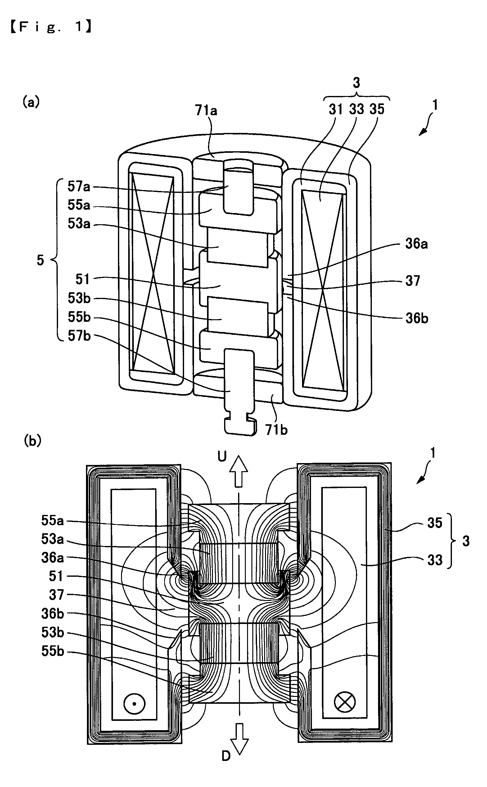
[0069]FIG. 1(a) is an explanatory perspective cross-sectional view showing a portion of a linear actuator to which the present invention may be applied, which is cut in an axial direction and viewed from obliquely above. FIG. 1(b) is an explanatory view showing the magnetic lines of force in the linear actuator.

[0070]In FIGS. 1(a) and 1(b), a linear actuator 1 in accordance with an embodiment is used in a valve device or a compressor device for supplying various fluids. The linear actuator 1 includes a cylindrical fixed body 3 and a roughly cylindrical movable body 5 which is disposed in the inner side of the fixed body 3. The fixed body 3 includes a coil 33 wound around a bobbin 31 in a ring-shaped manner and a fixed body side yoke 35 which is formed such that one front end part 36a and the other front end part 36b face each other in an axial direction via a ...


PUM


Abstract

A linear actuator may include a fixed body having a coil wound around in a ring-shaped manner and a movable body. The movable body may include a first movable body side yoke which is disposed on the inner side of the coil and a pair of magnets which is laminated on both sides in an axial direction of the first movable body side yoke such that the same polarities of the magnets face the first movable body side yoke. The movable body may be driven in the axial direction. The linear actuator may be applied to a valve device and a pump device.

Description

CROSS REFERENCE TO RELATED APPLICATION[0001]The present invention claims priority under 35 U.S.C. §119 to Japanese Application No. 2004-347701 filed Nov. 30, 2004, Japanese Application No. 2004-365924 filed Dec. 17, 2004, and Japanese Application No. 2005-43141 filed Feb. 18, 2005, each of which are incorporated herein by reference.FIELD OF THE INVENTION[0002]An embodiment of the present invention may relate to a linear actuator and a valve device using the linear actuator. Further, an embodiment of the present invention may relate to a pump device and, more specifically, a pump device in which an inflow port and a plurality of outflow ports are opened in a main body of the pump device.BACKGROUND OF THE INVENTION[0003]In a conventional linear actuator which is used in a valve device in a pump or the like, a solenoid is used without using a magnet. However, this type of linear actuator has a problem that when its size is made smaller, its thrust remarkably decreases as its volume dec...

Claims


Application Information

Patent Timeline
Patent Type & Authority Patents(United States)
IPC IPC(8): F04B17/00
CPCF04B17/042F04B35/045F04B43/025F04B43/04H01F7/1615H02K33/16H01F2007/086H01F2007/1692F04B35/04F04B39/10F05B2210/14
Inventor MURAMATSU, KENJISUGIHARA, HIROSHITAKASAWA, KIYOTSUGUYOKOZAWA, MITSUO
Owner SANKYO SEIKI MFG CO LTD
Why Eureka
Try Eureka