Scanned source oriented nanofiber formation

a nanofiber and source technology, applied in the field of nanofiber formation, can solve the problems of not being able to fabricate nanofibers on a planar surface, and it is difficult if not impossible to integrate nanofibers with microfabricated structures for such applications

Inactive Publication Date: 2009-05-26
CORNELL RES FOUNDATION INC
View PDF170 Cites 16 Cited by
  • Summary
  • Abstract
  • Description
  • Claims
  • Application Information

AI Technical Summary

Problems solved by technology

However, this approach does not permit fabricating of nanofibers on a planar surface.
Therefore, it is difficult if not impossible to integrate nanofibers with microfabricated structures for such applications.

Method used


Image

  • Scanned source oriented nanofiber formation
  • Scanned source oriented nanofiber formation
  • Scanned source oriented nanofiber formation

Examples


Embodiment Construction

[0025]In the following description, reference is made to the accompanying drawings that form a part hereof, and in which is shown by way of illustration specific embodiments in which the invention may be practiced. These embodiments are described in sufficient detail to enable those skilled in the art to practice the invention, and it is to be understood that other embodiments may be utilized and that structural, logical and electrical changes may be made without departing from the scope of the present invention. The following description is, therefore, not to be taken in a limited sense, and the scope of the present invention is defined by the appended claims.

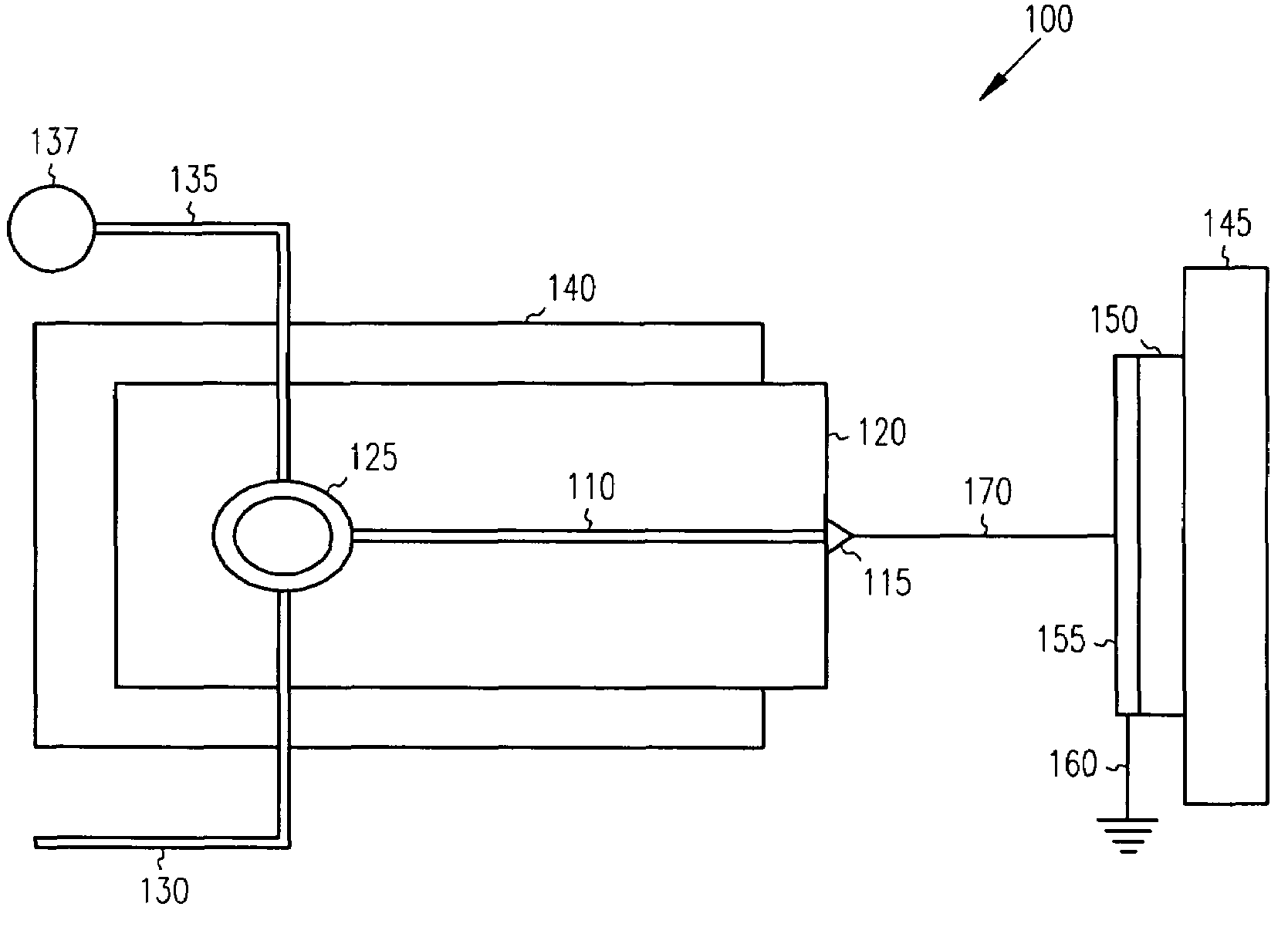
[0026]A microfluidic electrospray system is shown at 100 in FIG. 1. A microfluidic channel 110 is coupled at one end to a triangular tip 115, acting as a source for formation of nanofibers. Both are supported by a substrate 120. A reservoir 125 provides a polymer solution in one embodiment to the channel 110 and to the tip 115...


PUM

PropertyMeasurementUnit
surface velocityaaaaaaaaaa
distanceaaaaaaaaaa
diameteraaaaaaaaaa

Abstract

Nanofibers are formed using electrospray deposition from microfluidic source. The source is brought close to a surface, and scanned in one embodiment to form oriented or patterned fibers. In one embodiment, the surface has features, such as trenches on a silicon wafer. In further embodiments, the surface is rotated to form patterned nanofibers, such as polymer nanofibers. The nanofibers may be used as a mask to create features, and as a sacrificial layer to create nanochannels.

Description

RELATED APPLICATION[0001]This application claims priority from U.S. Provisional Application No. 60 / 506,214; filed on Sep. 26, 2003; which is incorporated herein by reference.[0002]This application is related to U.S. patent application Ser. No. 10 / 394,757 (entitled Electrospray Emitter for Microfluidic Channel, filed May 21, 2003).GOVERNMENT FUNDING[0003]The invention described herein was made with U.S. Government support under Grant Number ECS-9876771 awarded by National Science Foundation (NSF) / Nanobiotechnology Center (NBTC). The United States Government has certain rights in the invention.FIELD OF THE INVENTION[0004]The present invention relates to forming nanofibers, and in particular to forming oriented nanofibers using a scanned source.BACKGROUND OF THE INVENTION[0005]Nanoscale materials, such as nanowires, nanotubes and nanofibers have gained more attention recently because of their unique electrical, optical and mechanical properties. Fabrication of oriented nanofibers on a ...

Claims


Application Information

Patent Timeline
Patent Type & Authority Patents(United States)
IPC IPC(8): B05D1/04B05D1/06D01F6/64D01F6/66
CPCB82Y30/00D01D5/0069D01F6/64C23F17/00D01F6/66Y10T428/24562Y10S977/856Y10S977/888
Inventor CRAIGHEAD, HAROLD G.KAMEOKA, JUN
Owner CORNELL RES FOUNDATION INC
Why Eureka
Try Eureka