Systems and methods for assisting start of electrodeless RF discharge in a ring laser gyro

a technology of laser gyro and ring laser, which is applied in the direction of speed measurement using gyroscopic effects, lasers, instruments, etc., can solve the problems of generating unwanted noise, oversized circuits with unnecessary complexity for normal sustained operation,

Active Publication Date: 2009-05-26
HONEYWELL INT INC
View PDF6 Cites 3 Cited by
  • Summary
  • Abstract
  • Description
  • Claims
  • Application Information

AI Technical Summary

Problems solved by technology

Although the systems shown in the ′772 patent and the ′894 patent alleviate some of the impedance matching problems of the prior art, they include oversized circuits with unnecessary complexity for the normal sustained operation after the gas medium in the laser is ignited, such as in a ring laser gyro, thus producing unwanted noise.

Method used


Image

  • Systems and methods for assisting start of electrodeless RF discharge in a ring laser gyro
  • Systems and methods for assisting start of electrodeless RF discharge in a ring laser gyro

Examples


Embodiment Construction

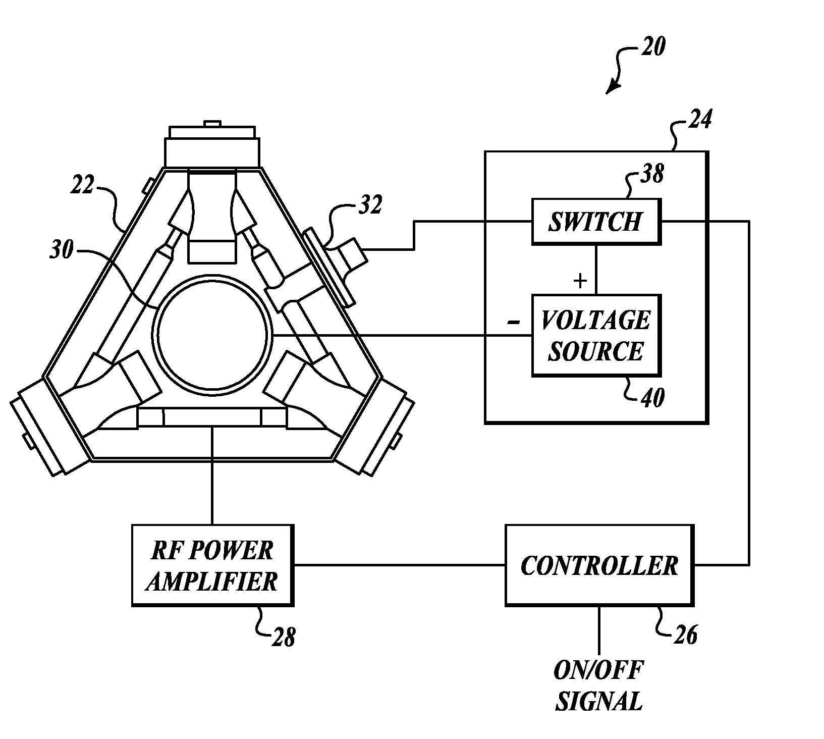
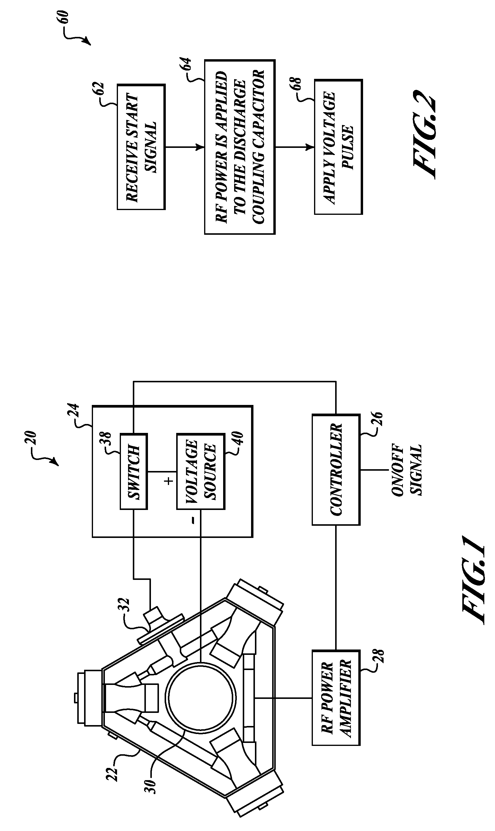
[0015]FIG. 1 illustrates a schematic diagram of an electrodeless RF discharge ring laser gyro system 20. The system 20 includes an electrodeless ring laser gyro (RLG) 22, a starting circuit 24, a controller 26, and an RF power source 28.

[0016]The starting circuit 24 includes a switch 38 and a voltage source 40. In one embodiment, the switch 38 is attached between a metallic fill tube 32 of the RLG 22 and the voltage source 40. The voltage source 40 is also connected to a dither motor 30 of the RLG 22. The switch 38 is controlled by the controller 26. The controller 26 also controls the RF power source 28. The RF power source 28 is connected to a discharge coupling capacitor (not shown) that is located external to a leg of a laser gas-discharge cavity 44 of the RLG 22.

[0017]When the controller 26 initially receives an on signal from some external source, such as an on / off switch or a user interface, the controller 26 causes the switch 38 to close for a predetermined period of time. T...


PUM


Abstract

Systems and methods for starting and operating an electrodeless RF discharge ring laser gyro. In one example, an electrodeless RF discharge ring laser gyro system includes a ring laser gyro, a starting circuit, an RF power source, and a controller. The starting circuit is electrically connected to the ring laser gyro. The starting circuit applies an electrial pulse to the ring laser gyro. The RF power source is electrically connected to the ring laser gyro. The RF power source applies an operating power to the ring laser gyro. The controller is electrically connected to the RF power source and the starting circuit. The controller controls operation of the starting circuit and the RF power source.

Description

BACKGROUND OF THE INVENTION[0001]A radio frequency (RF)-excited gas laser produces laser power when a gas medium within the laser is excited by RF power applied between a pair of electrodes. The RF energy is delivered to the laser electrodes by a drive system that includes an RF energy source and a transmission line. The impedance of the gas medium typically is initially 1,000-2,000 ohms before the gas medium in the laser is ignited and approximately 200 ohms after ignition.[0002]One system that overcomes some of the problems of prior art drive systems for RF-excited gas lasers is disclosed in U.S. Pat. No. 4,837,772 (the ′772 patent) to Laakmann. The system shown in the ′772 patent includes a lumped constant matching system connected directly between a transistor of the RF energy source and the laser. In addition, the ′772 patent discloses a coaxial cable connecting the laser to the input of the RF energy source transistor to create a feedback path. Such a system is “self-oscillati...

Claims


Application Information

Patent Timeline
Patent Type & Authority Patents(United States)
IPC IPC(8): G01C19/64
CPCG01C19/661H01S3/0975H01S3/0835
Inventor THORLAND, RODNEY H.OLLESTAD, GEORGE R.
Owner HONEYWELL INT INC
Why Eureka
Try Eureka