
Portable terminal unit and sound reproducing system using at least one portable terminal unit

Inactive Publication Date: 2009-05-26
NEC CORP
View PDF17 Cites 100 Cited by
  • Summary
  • Abstract
  • Description
  • Claims
  • Application Information

AI Technical Summary

Benefits of technology

[0008]Therefore, it is an object of the present invention to provide a sound reproducing system and method of portable terminal units in which stereophonic sound, surround sound, home theater sound and the like can be conveniently and comfortably reproduced by using a simple structure.
[0009]It is another object of the present invention to provide a sound reproducing system and method of portable terminal units in which a plurality of persons can listen to stereophonic sound, surround sound, home theater sound and the like conveniently and comfortably by using a simple structure.
[0010]It is still another object of the present invention to provide a sound reproducing system and method of portable terminal units in which good stereophonic effect can be realized by using a simple structure.

Problems solved by technology

However, in the above-mentioned conventional technologies, there is a problem that only a person who wears the headphones can listen to stereophonic music, surround sound and the like, but other surrounding persons can not listen thereto.
However, since the portable terminal unit usually has a small size, there occurs another problem that crosstalk becomes large and it is difficult to obtain sufficient stereophonic effect.
Further, there occurs still another problem that, in order to listen to the sound such as the surround sound and the like, it is necessary to connect other speakers to the portable terminal unit.

Method used


Image

  • Portable terminal unit and sound reproducing system using at least one portable terminal unit
  • Portable terminal unit and sound reproducing system using at least one portable terminal unit
  • Portable terminal unit and sound reproducing system using at least one portable terminal unit

Examples


first embodiment

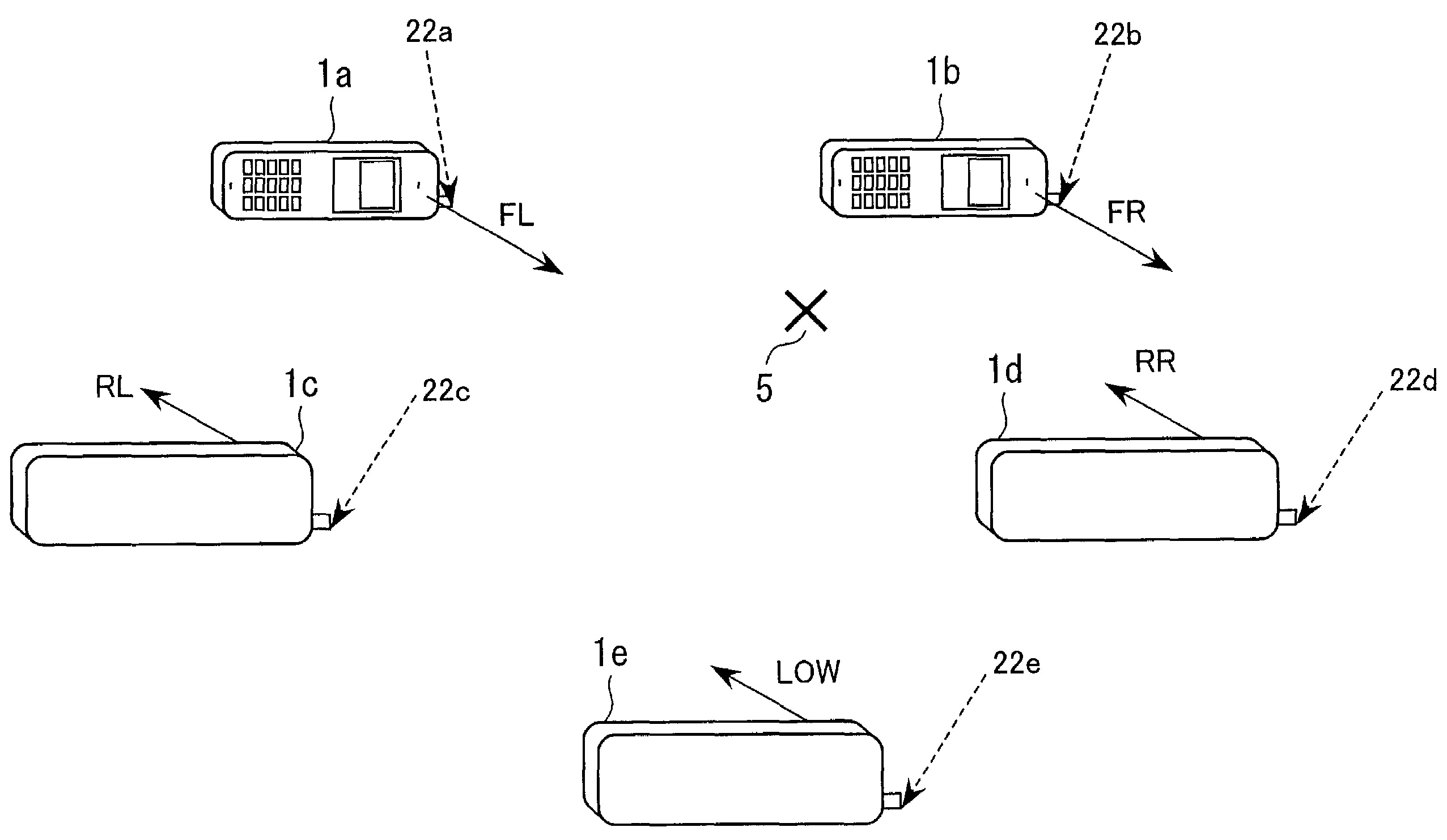
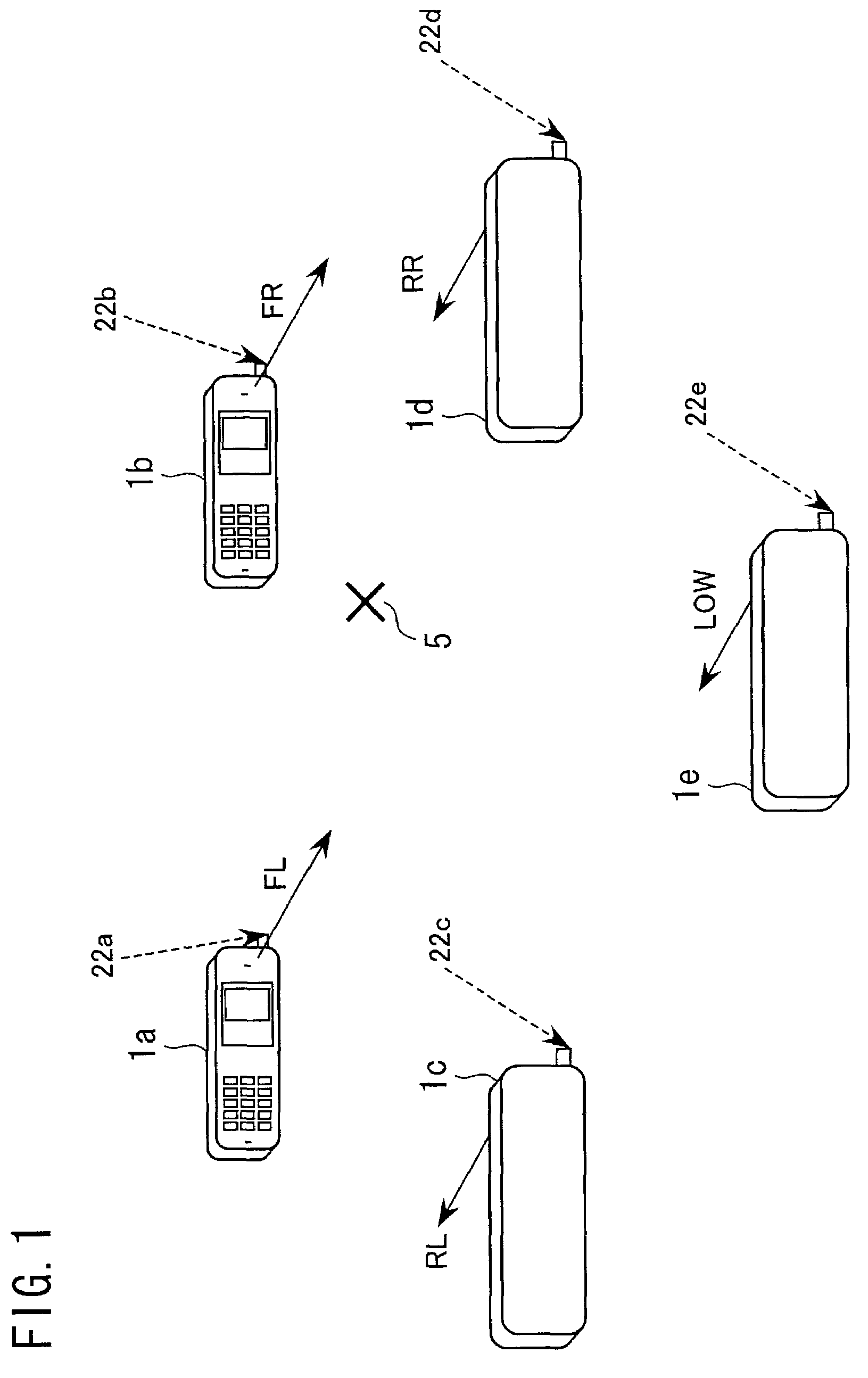
[0079]FIG. 1 is an illustration showing a schematic structure of a sound reproducing system of portable terminal units according to the present invention. FIG. 1 shows an example of a sound reproducing system in which each of a plurality of portable terminal units receives radio waves individually.

[0080]First, as shown in the drawing, the sound reproducing system of portable terminal units according to the first embodiment comprises five portable terminal units 1a, 1b, 1c, 1d and 1e.

[0081]The five portable terminal units 1a, 1b, 1c, 1d and 1e are disposed on the periphery of a listener or listeners 5, and reproduce surround sound including low frequency range sound.

[0082]That is, among the five portable terminal units 1a, 1b, 1c, 1d and 1e disposed respectively at mutually separate locations, the portable terminal unit 1a reproduces front-left sound FL, the portable terminal unit 1b reproduces front-right sound FR, the portable terminal unit 1c reproduces rear-left sound RL, the po...

second embodiment

[0136]FIG. 4 is an illustration showing a schematic structure of a sound reproducing system of portable terminal units according to the present invention.

[0137]As shown in FIG. 4, the sound reproducing system of portable terminal units according to the second embodiment has a structure in which a television set (TV) 120 is added to the sound reproducing system of the first embodiment. In the television set 120 disposed approximately between a portable terminal unit 1a and a portable terminal unit 1b, center sound data and image data are received and reproduced.

[0138]The television set 120 may have a function of a high frequency center unit, or may have a function of a sound center for vocals and speeches.

[0139]It is also possible to display the same or different images in a part of or all of the screens of the portable terminal units 1a, 1b, 1c, 1d and 1e, and also in the television set 120.

[0140]An explanation will now be made on schematic structures of the sound reproducing system...

third embodiment

[0167]FIG. 7 is an illustration showing a schematic structure of a sound reproducing system of portable terminal units according to the present invention. FIG. 7 shows an example of a sound reproducing system in which portable terminal units are serially coupled together.

[0168]As shown in FIG. 7, the sound reproducing system of portable terminal units according to the third embodiment has a structure comprising five portable terminal units 1a, 1b, 1c, 1d and 1e which are disposed around a listener or listeners 5 and which reproduce surround sound. Only by using the portable terminal unit 1a, surround sound data FL, FR, RL and RR, sound data of low frequency sound LOW and high frequency sound HIGH, and image data is received via radio waves 22a. From the portable terminal unit 1a, surround sound data FR, RL and RR, sound data of low frequency sound LOW and high frequency sound HIGH, and image data are sequentially transmitted, via cables 21a, 21b, 21c and 21d, to the portable termina...


PUM


Abstract

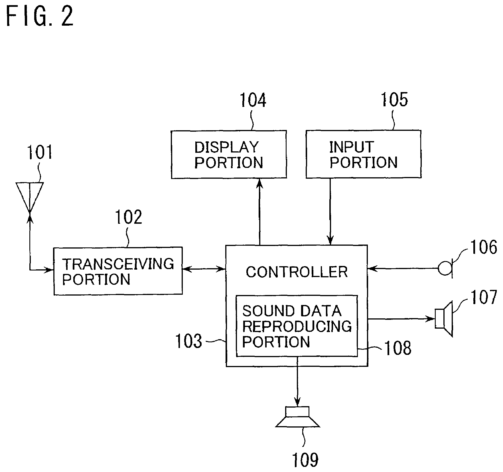
A sound reproducing system including at least one portable terminal unit which acquires data including sound data. For example, the data may be multimedia data and is acquired from data delivery service and the like. Each of the at least one portable terminal unit comprises: a loudspeaker for reproducing sound from the sound data; and a sound data reproducing portion which makes the loudspeaker reproduce the sound based on the sound data and in cooperation with at least one sound devices. The sound devices may be other portable terminal units. By using a plurality of portable terminal units, it becomes possible to reproduce stereophonic sound, surround sound, and the like. It is also possible to reproduce image together with such sound.

Description

FIELD OF THE INVENTION[0001]The present invention relates generally to a portable terminal unit including a radio telephone such as a portable telephone, a personal handy phone system (PHS), a cordless telephone, a child unit of a party line, a personal digital assistants (PDA) and the like. More particularly, the present invention relates to a sound reproducing system and method of a portable terminal unit in which portable terminal units are mutually and organically coupled, or portable terminal unit or units are organically coupled with other audio system to realize high quality sound reproduction.BACKGROUND OF THE INVENTION[0002]Recently, portable terminal units such as portable telephones and the like become remarkably popular, and are carried by many people when they go outside.[0003]Also, the portable terminal unit has become capable of providing multimedia services. Because of an increase in memory capacity, incorporation of storage media, an increase in a communication spee...

Claims


Application Information

Patent Timeline
IPC IPC(8): G06F17/00H04H40/00G10K15/02H04R5/02H04B7/26H04M1/00H04R5/033H04S1/00H04S5/02
CPCH04S1/00
Inventor KOMURA, TATSUMITAKANASHI, NOBUAKI
Owner NEC CORP
Learn More