Wheel carrier unit comprising an integrated brake application unit

a technology of integrated brake application and wheel carrier, which is applied in the direction of braking system, brake disc, transportation and packaging, etc., can solve the problems of partial or complete failure of the braking system, and achieve the effects of low weight, reduced assembly cost and associated costs

Inactive Publication Date: 2009-06-02
DAIMLER AG
View PDF13 Cites 3 Cited by
  • Summary
  • Abstract
  • Description
  • Claims
  • Application Information

AI Technical Summary

Benefits of technology

[0006]The wheel carrier unit according to the invention has a brake cylinder on its side remote from the wheel. This has the advantage that the brake cylinder is arranged on the side of the wheel carrier on which the brake lines are also situated. The brake lines do not have to extend through the wheel carrier unit. Opposite the wheel, the brake cylinder is protected by the wheel carrier unit. This means that the hydraulic, pneumatic or electrical side of the brake system is separated by the wheel carrier unit from the mechanical force transmission of the wheel brake. In a hydraulic brake system this has the advantage that the wheel brake is not adversely exposed to fouling by the hydraulic part, for example when changing the brake fluid or bleeding the brakes, or when leaks occur in the hydraulic brake system. In extreme cases brake fluid could otherwise get onto the brake linings and could lead to a partial or complete failure of the braking system.
[0013]It is advantageous to form the wheel carrier unit from a casting. The advantage to this is that a high-strength geometrical design will permit the use of lesser grade materials. In this way it is possible to provide an inexpensive wheel carrier unit that is capable of meeting high load requirements.

Problems solved by technology

In extreme cases brake fluid could otherwise get onto the brake linings and could lead to a partial or complete failure of the braking system.

Method used


Image

  • Wheel carrier unit comprising an integrated brake application unit
  • Wheel carrier unit comprising an integrated brake application unit
  • Wheel carrier unit comprising an integrated brake application unit

Examples


Embodiment Construction

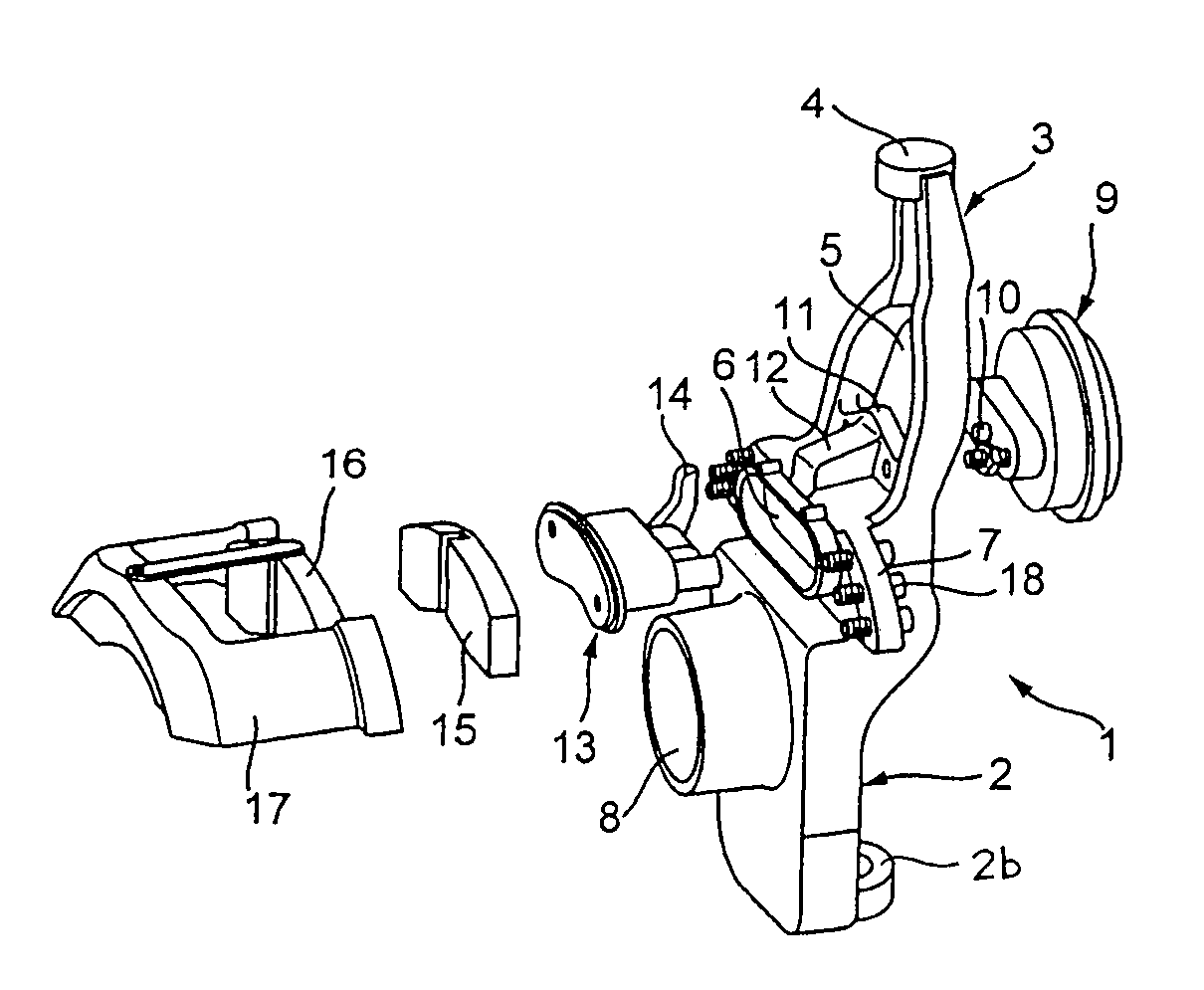
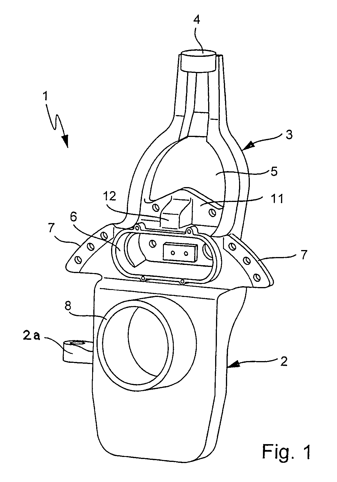
[0018]FIG. 1 shows the wheel carrier unit 1 according to the invention. The wheel carrier unit 1 has a basic wheel carrier member 2 and a support arm 3 extending therefrom, which connects the wheel carrier unit 1 via axle links to a body of a vehicle.

[0019]The support arm 3 is of forked design with a connecting structure 4 arranged at the top, from which two lateral support arms extend downwards. The basic support arm is oriented approximately vertically and inclined slightly in the direction of the lateral support arms towards the center of the vehicle. The lateral support arms extend downwards from the connecting structure 4 towards the vehicle wheel.

[0020]In the embodiment shown in FIG. 1 the connecting structure 4 has a mounting bore (not shown). By means of a bolt or the like, the support arm 3 is fixed to an axle link by way of the connecting structure 4. In this way the wheel carrier unit 1 is attached to a vehicle body.

[0021]The two lateral support arms of the forked support...


PUM


Abstract

In a wheel carrier unit comprising a basic wheel carrier member, a support member connecting the basic wheel carrier member to a vehicle body by way of axle links, and a brake cylinder arranged thereon, the brake cylinder is disposed on the side of the wheel carrier unit remote from the wheel location and a housing for a brake application unit serving as mechanical force transmission unit is formed on the opposite side of the wheel carrier unit.

Description

[0001]This is a Continuation-In-Part Application of International Application PCT / EP2004 / 006569 field Jun. 18, 2004 and claiming the priority of German Application 103 28 679.9 filed Jun. 26, 2003.BACKGROUND OF THE INVENTION[0002]The invention relates to a wheel carrier unit with an integrated brake force application structure, including a basic wheel carrier, an axle support structure connecting the wheel carrier to a vehicle body and a brake cylinder mounted on the axle support structure.[0003]EP 0 944 509 B1 discloses a wheel suspension connecting element for a wheel of a motor vehicle, which comprises the cylinder of a piston-cylinder unit of a disc brake, that is integrally formed with the connecting element.[0004]It is the object of the present invention is to specify a lightweight wheel carrier unit which is inexpensive to manufacture and which takes up little overall space.SUMMARY OF THE INVENTION[0005]In a wheel carrier unit comprising a basic wheel carrier member, an axle ...

Claims


Application Information

Patent Timeline
Patent Type & Authority Patents(United States)
IPC IPC(8): B62D7/18F16D65/12B60T1/06F16D65/14
CPCB60T1/062B60G2206/50F16D2055/0012F16D2121/02F16D2125/32
Inventor LESCH, MARTINMAUZ, UWEQUINGER, CHRISTIAN
Owner DAIMLER AG
Why Eureka
Try Eureka