Multi-rotor aircraft with multiple shafts arranged in staggered mode

A multi-rotor aircraft and layout technology, which is applied to unmanned aircraft, aircraft, rotorcraft, etc., can solve the problems of large flight resistance, large volume, and low paddle efficiency

Active Publication Date: 2020-07-28
SHANDONG DINGFENG AVIATION TECH CO LTD
View PDF4 Cites 0 Cited by
  • Summary
  • Abstract
  • Description
  • Claims
  • Application Information

AI Technical Summary

Problems solved by technology

[0008] The technical problem to be solved by the present invention is to provide a multi-rotor aircraft with a multi-axis dislocation layout in order to overcome the defects of the multi-rotor aircraft in the prior art that have greater flight resistance, larger volume, and lower paddle efficiency under the same load capacity.

Method used


Image

  • Multi-rotor aircraft with multiple shafts arranged in staggered mode
  • Multi-rotor aircraft with multiple shafts arranged in staggered mode
  • Multi-rotor aircraft with multiple shafts arranged in staggered mode

Examples


Embodiment 1

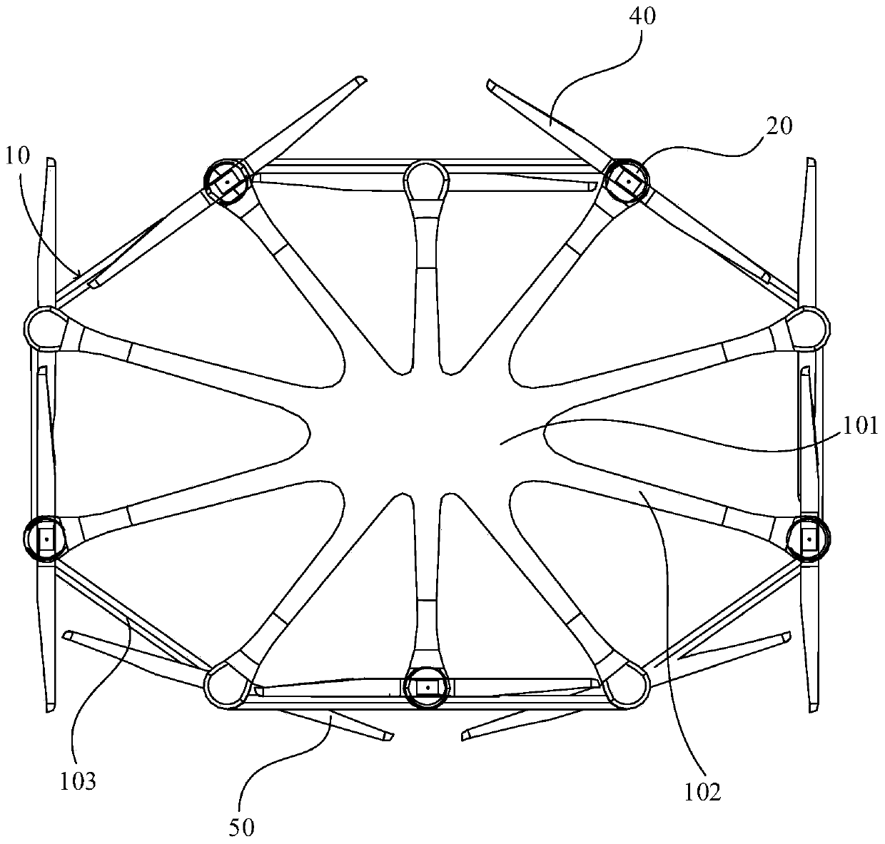
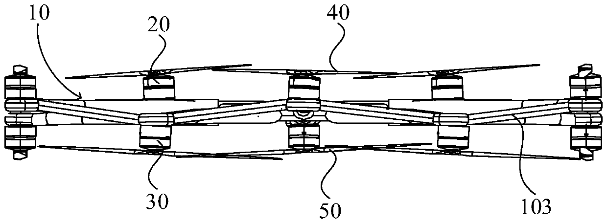
[0059] This embodiment discloses a multi-rotor aircraft with multi-axis dislocation layout, such as Figure 1-2 As shown, the multi-rotor aircraft includes a frame 10 , a plurality of upper power sources 20 , a plurality of lower power sources 30 , a plurality of upper blades 40 and a plurality of lower blades 50 . A plurality of upper blades 40 are arranged at intervals, and are connected above the frame 10 through a plurality of upper power sources 20 . A plurality of lower blades 50 are arranged at intervals, and are connected to the bottom of the frame 10 through a plurality of lower power sources 30 . Wherein, along the projection direction of the frame 10 , a plurality of upper paddles 40 and a plurality of lower paddles 50 are alternately arranged. Along the projection direction of the frame 10 , the centers of the plurality of upper paddles 40 and the centers of the lower paddles 50 are located on the same flat geometric figure. Wherein, the above-mentioned projectio...

Embodiment 2

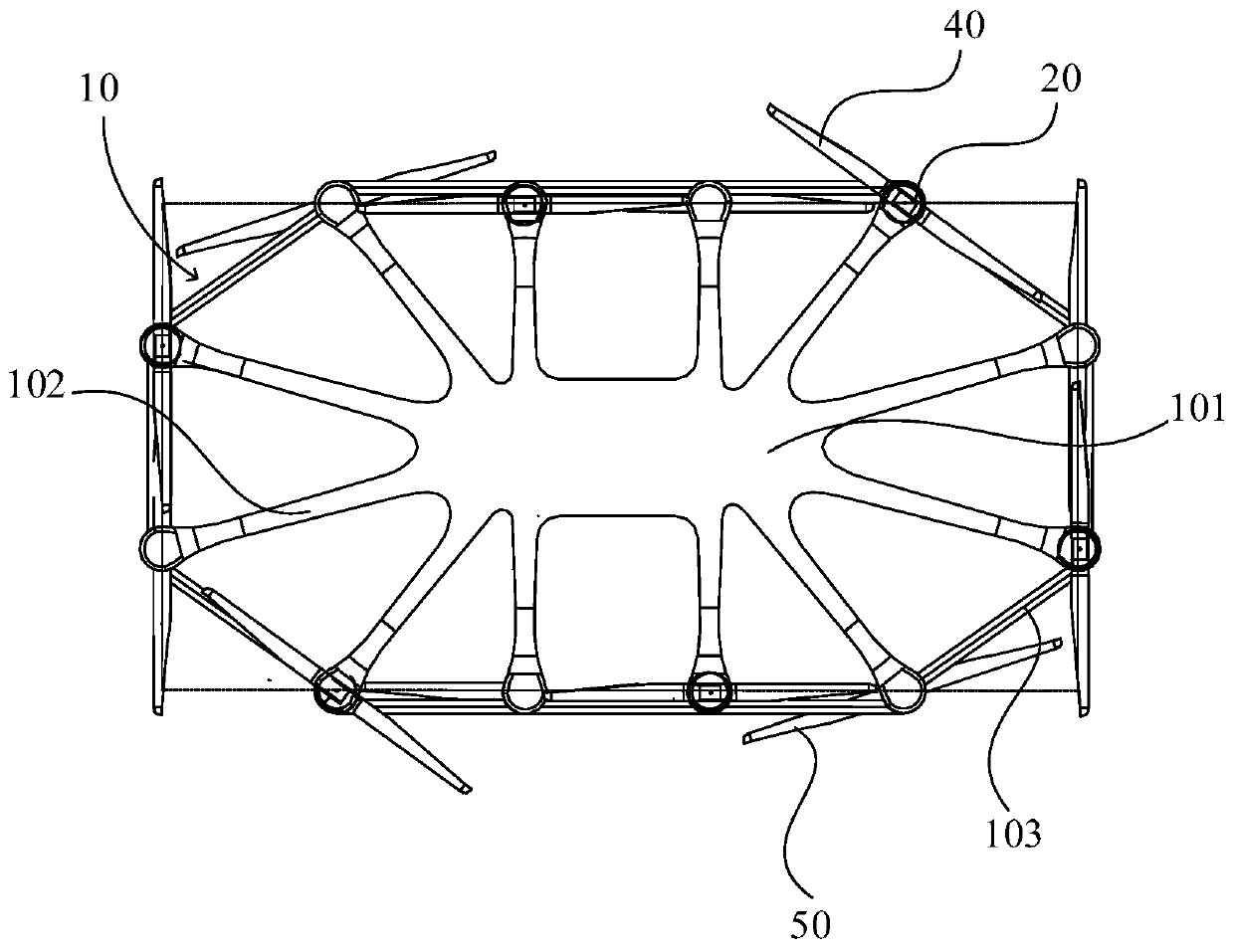
[0087] The structure of the multi-rotor aircraft with multi-axis dislocation layout in this embodiment is basically the same as the structure of the multi-rotor aircraft with multi-axis dislocation layout in Embodiment 1, the difference mainly lies in the number of blades and the number of power sources. Wherein, the same reference numerals in this embodiment and the first embodiment refer to the same elements.

[0088] Such as image 3 As shown, the number of the upper blades 40 and the lower blades 50 is 6, correspondingly, the number of the upper power source 20 and the lower power source 30 is also 6, that is, the number of multi-rotor aircraft in this embodiment is 12 12-axis aircraft. image 3 shows that the centers of the 12 paddles lie on the same rectangle.


PUM


Abstract

The invention discloses a multi-rotor aircraft with multiple shafts arranged in a staggered mode. The multi-rotor aircraft comprises a rack, a plurality of upper-layer power sources, a plurality of lower-layer power sources, a plurality of upper-layer paddles and a plurality of lower-layer paddles. The upper-layer paddles are arranged at intervals and connected to the upper portion of the rack through the plurality of upper-layer power sources. The plurality of lower-layer paddles are arranged at intervals and are connected to the lower part of the rack through the plurality of lower-layer power sources. The multiple upper-layer paddles and the multiple lower-layer paddles are arranged in a staggered mode in the projection direction of the rack. The centers of the upper-layer paddles and the centers of the lower-layer paddles are located on the same flat geometric figure in the projection direction of the rack. Under the same loading capacity, the multi-rotor aircraft can obviously reduce the flight resistance and volume and improve the propeller efficiency. Besides, the multi-rotor aircraft can also meet the high load requirement under the condition that influence on the size andthe weight is small, and the requirement of the multi-rotor aircraft for transportation equipment is low.

Description

technical field [0001] The present application relates to the technical field of multi-rotor aircraft, in particular to a spider-like multi-rotor aircraft with compact structure and multi-axis dislocation layout. Background technique [0002] Among the multi-axis rotorcraft in the prior art, the designs of 4-axis and 8-propellers and 8-axis and 8-propellers are more common, and there are various frame structures such as X-type, H-type, and Y-type according to different design requirements and layout conditions. [0003] Among them, the 4-axis 8-blade multi-rotor aircraft is a coaxial design, the power shaft of the motor corresponding to the 4 blades of the upper layer and the power shaft of the motor corresponding to the 4 blades of the lower layer correspond to the same line one by one, and the upper and lower blades The pitch is small, the upper and lower blades overlap in the projection direction, and the paddle efficiency is low. In addition, in this multi-rotor aircraf...

Claims


Application Information

Patent Timeline
Patent Type & Authority Applications(China)
IPC IPC(8): B64C27/08B64C27/467B64C1/06
CPCB64C27/08B64C27/467B64C1/06B64C39/024B64U10/13B64U30/20Y02T50/40
Inventor 田瑜
Owner SHANDONG DINGFENG AVIATION TECH CO LTD
Why Eureka
Try Eureka