
Lamp unit and projection display apparatus

a technology of projection display and lamp unit, which is applied in the direction of lighting and heating equipment, instruments, transportation and packaging, etc., can solve the problems of noisy noise, increased noise value of small projection display equipment, and high rotational speed fan grating noise, so as to reduce the load of the exhaust fan, reduce the amount of air required, and increase the static pressure

Inactive Publication Date: 2009-06-02
NEC DISPLAY SOLUTIONS LTD
View PDF18 Cites 5 Cited by
  • Summary
  • Abstract
  • Description
  • Claims
  • Application Information

AI Technical Summary

Benefits of technology

"The present invention provides a lamp unit that allows for efficient cooling of a light source lamp using a small fan with high static pressure. This reduces the amount of air required for cooling and keeps the exhaust fan at a low rotational speed to minimize noise. The lamp unit includes a reflector holding member, a positioner, and an opening for connecting the reflector to the light source lamp. The lamp unit can be fixed to an optical unit and includes a cavity for cooling the light source lamp. The invention also includes a blower with a noise isolation cover and a ventilation hole for efficient cooling. The small high static pressure fan can be used for cooling down the light source lamp, reducing the size of the display apparatus and limiting the rotational speed of the exhaust fan to restrain noise levels."

Problems solved by technology

Since this cooling fan generates noise, an attempt to enhance cooling capabilities of an electronic device can result in a problem of noisiness caused by noise generated from the cooling fan.
The problem for a projection display device is the issue of how to reconcile a reduction in size with a reduction in noise which increases because of cooling mechanisms that are included in such devices in order to improve performance.
However, the related art techniques described above have the following problems.
The first problem is the increased noise value in a small projection display apparatus resulting from the need for rotating a plurality of mountable small axial flow fans in order to produce the amount of exhaust air required to cool the projection display apparatus which is equipped with a large heat source.
While this problem is in part caused by lack of an absolute amount of air provided by a small fan at an ordinary rotational speed, the problem is also largely affected by use of both the project apparatus and the exhaust fan for cooling the lamp which generates a large amount of heat.
Also, the rotation of the fan at high rotational speeds is likely to generate grating noise.
Therefore, even when the noise level is reduced, the noise is heard as annoying because of its grating nature.
Also, it is difficult to employ a silencer attached to the apparatus for restraining such noise, due to limitations in the size of the apparatus.
A second problem is difficulties in equipping a small projection display apparatus with a fan which has sufficient capabilities of cooling a lamp.
This problem stems from the fact that although the only way to provide required static pressure with a small fan is to sacrifice a certain amount of air, the conventional lamp cooling method involves increasing static pressure for ensuring a flow velocity required for cooling the lamp, whereas the amount of air cannot be reduced for cooling down generated heat.
A third problem lies in that even in JP-A-2005-62452 which discloses a technique for eliminating fine adjustments to a lamp optical axis, all cooling air does not pass through the cooling holes or intake port, so that portions of the cooling air which do not pass through the cooling holes or intake port become substantially useless, thus failing to effectively make use of a large amount of air.
This causes a problem of generating lauder noise, as in the case of the foregoing first problem.

Method used


Image

  • Lamp unit and projection display apparatus
  • Lamp unit and projection display apparatus
  • Lamp unit and projection display apparatus

Examples


Embodiment Construction

[0035]In the following, a lamp unit and a projection display apparatus according to one embodiment of the present invention will be described in detail with reference to the accompanying drawings. As illustrated in FIG. 4, in projection display apparatus 30 of the present invention, light emitted from light source lamp 1 of lamp unit 10 is reflected by reflector 2, and focused by focusing lens 31 of optical unit 5 to one point on color wheel 9 which is made up of color filters for selectively passing therethrough red, green, and blue light, respectively. Light passing through color wheel 9 is uniformized by a light tunnel formed in a box of rod integrator 32, and has its optical path changed by a mirror. After the change in the optical path, illumination light is irradiated to DMD (digital micro device) 7 through TIR (Total Internal Reflection) prism 6. Image light, which is light reflected by DMD 7, is projected onto a screen, not shown, through zoom projection lens 8. While the im...


PUM


Abstract

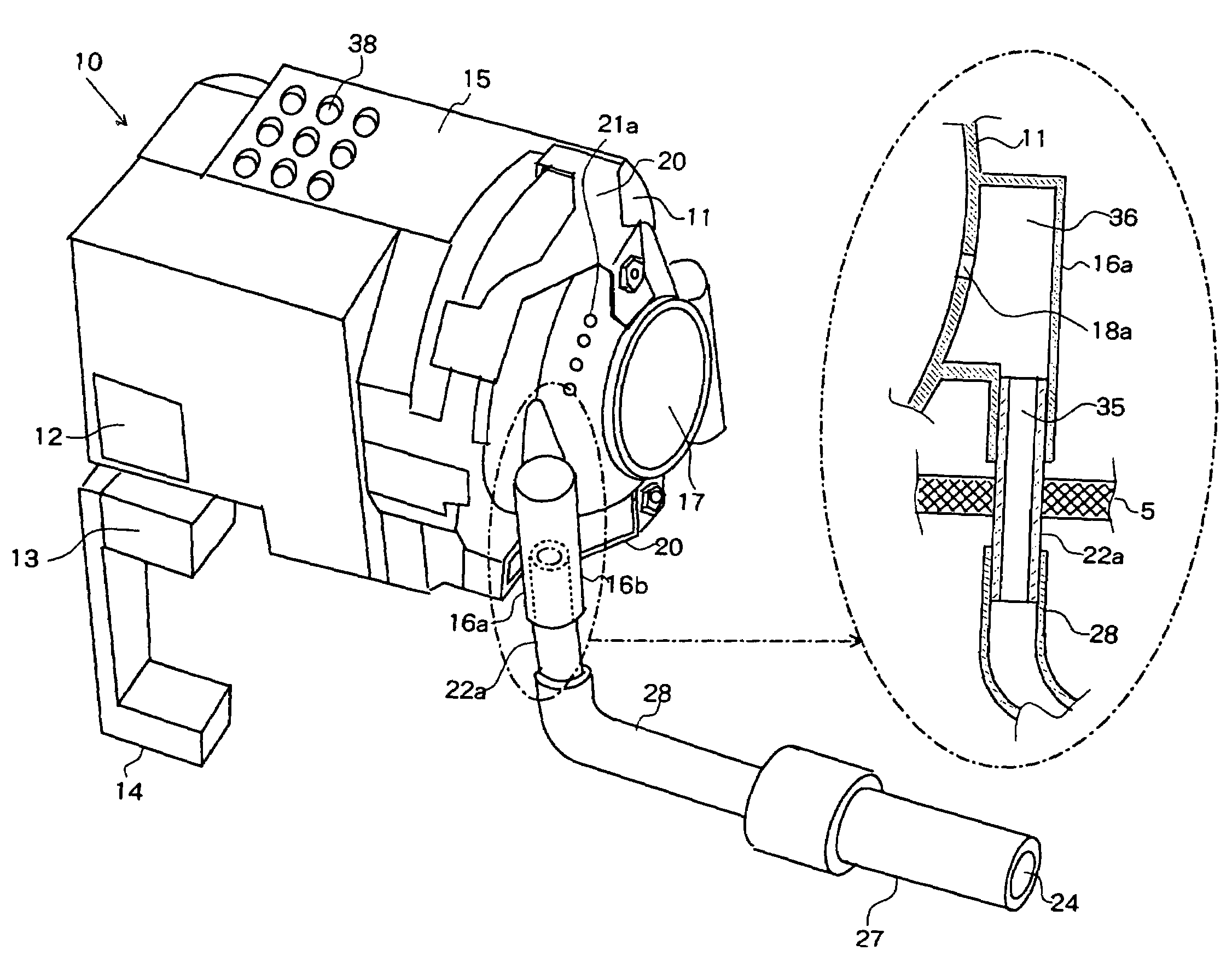
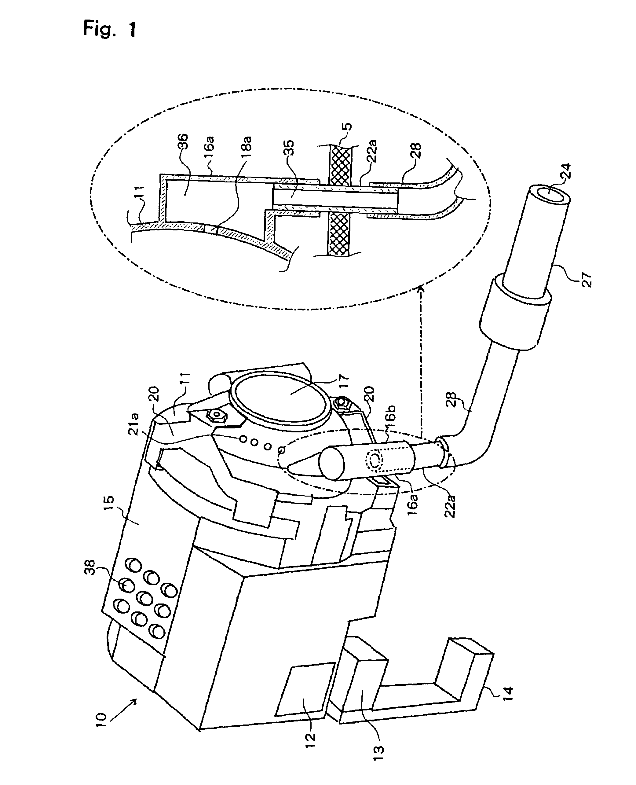
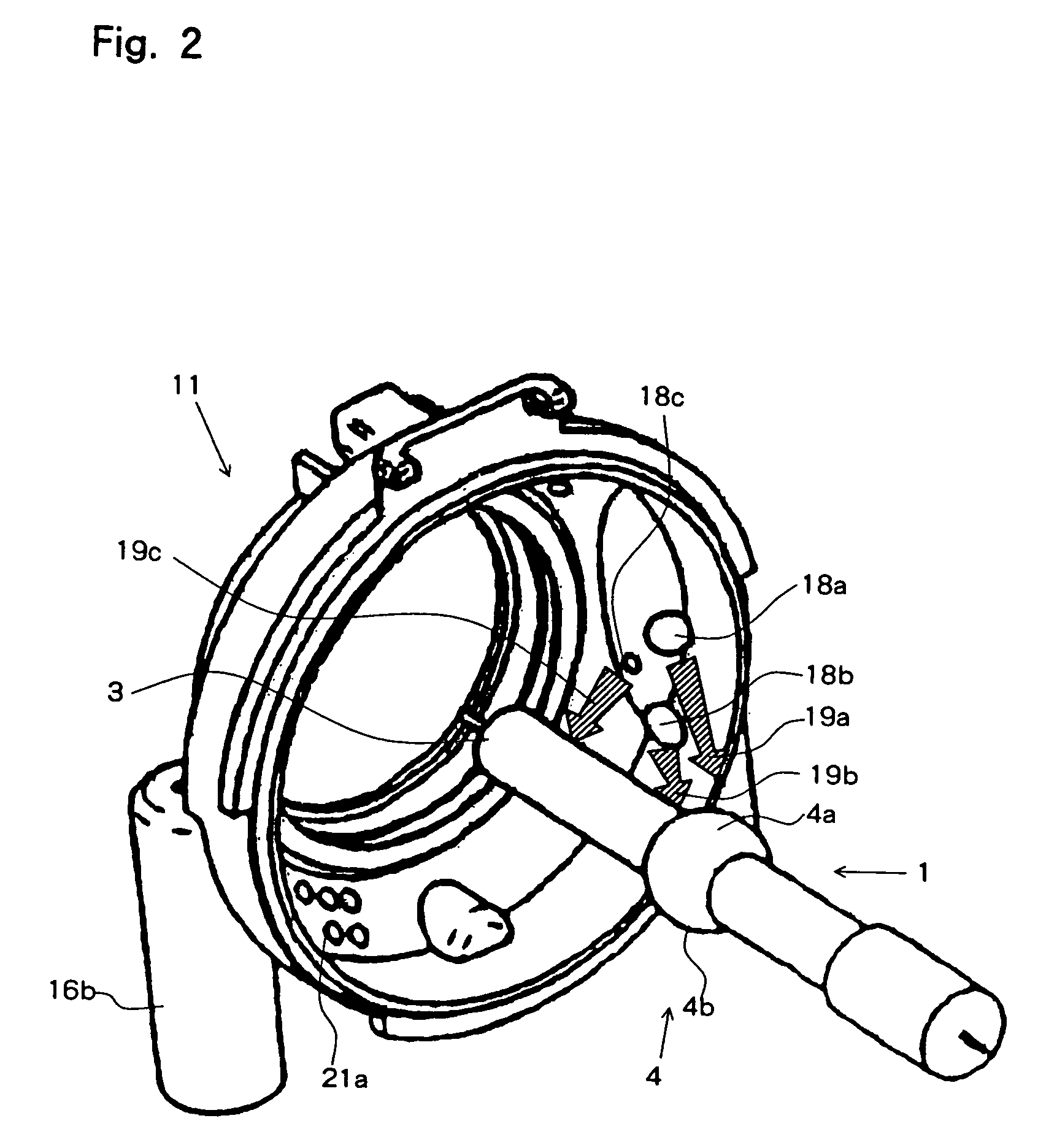
In lamp unit 10 having light source lamp 1, reflector 2 for reflecting light from light source lamp 1, reflector holding member 11, and reflector cover 15, a plurality of cooling holes 18a are formed in a region of reflector holding member 11 provided with lamp unit positioner 16a. Cooling holes 18a are open toward an upper bulb area, a lower bulb area, and a cathode of the light source lamp, respectively. Stud 22a for fixing reflector holding member 11 has a throughhole extending at the center thereof, so that cooling air fed from high static pressure blower 27 can be sent to cooling holes 18 through tube 28 and the throughhole of stud 22a, thus efficiently cooling the upper bulb area, lower bulb area, and cathode of light source lamp 1 in a concentrative manner with a small amount of air. Thus, the resulting lamp unit, provided by the present invention, can reduce the amount of air required for cooling the lamp, and can use a high static pressure and small fan.

Description

BACKGROUND OF THE INVENTION[0001]1. Field of the Invention[0002]The present invention relates to a lamp unit which comprises a light source unit for use in optical devices and the like, and a projection display apparatus which comprises the lamp unit, and more particularly, to a lamp unit which restrains noise generated by a cooling fan, and a projection display apparatus which is reduced in size and noise.[0003]2. Description of the Related Art[0004]Electric home appliances and the like are required be silent, so that a variety of technologies have been developed for reducing the generation of noise. This tendency goes beyond electric home appliances and is spreading to general electronic devices. In particular, for devices associated with personal computers, quiet operation is required not only for a magnetic disk drive, a CPU cooling unit, and a power supply cooling unit, which are components of a personal computer, but also for a projection display apparatus and the like which a...

Claims


Application Information

Patent Timeline
Patent Type & Authority Patents(United States)
IPC IPC(8): F21V29/00F21Y101/00
CPCF21V29/02G03B21/16F21V29/83
Inventor NISHIMURA, YOSHIFUMITAKAMATSU, HIROAKI
Owner NEC DISPLAY SOLUTIONS LTD
Learn More