Ultra-thin motor structure

a micro-motor, ultra-thin technology, applied in the direction of generator/motor, magnetic circuit rotating parts, magnetic circuit shape/form/construction, etc., can solve the problems of generating torque ripples, uneven rotation or vibration noise of the motor, and bottlenecks in the development of all these micro-motors of the prior art, and achieve the effect of increasing copper loss

Active Publication Date: 2009-06-02
METAL INDS RES & DEV CENT
View PDF3 Cites 6 Cited by
  • Summary
  • Abstract
  • Description
  • Claims
  • Application Information

AI Technical Summary

Benefits of technology

[0009]In view of the problems of the conventional technique described above, the present invention provides an ultra-thin motor structure for solving the disadvantage of conventional motors having a magnet and a great deal of magnetic conducting material, i.e., solving the magnetic cogging and torque ripple of the motor when operating and the difficulty in thinning of the motor, and meanwhile, overcoming the disadvantage of the conventional motor of increased copper loss caused by conductivity decline of the copper wire.
[0011]An ultra-thin motor structure of the present invention is provided with the following advantages over conventional methods, and the significant function improvements described below.
[0012]1. The present invention is an ultra-thin motor structure, as compared with various motor components of the conventional motor structure, is made using a micro / meso metal forming technique, improving the assembly and mass-production of the motor, satisfying demands for thinning and performance of the motor, and significantly reducing production costs.
[0013]2. According to an ultra-thin motor structure of the present invention, the plurality of coils of the winding plate are formed by a micro electroforming process or etching process, so that coil diameters of different micro-nanometer sizes can be made, and the wire density is improved. Therefore, compared with the conventional motor structure, the thickness of the motor windings can be effectively controlled to thin the motor and copper loss is reduced.
[0014]3. According to an ultra-thin motor structure of the present invention, the coil winding region of the ultra-thin motor structure is rhombus-shaped or kite-shaped. The wire width and height of the coils formed by an electroforming process or etching process are of micro-nanometer scale, so that compared with conventional sector-shaped, round-shaped, or triangle-shaped air-gap motors, the magnetic flux density can be enhanced significantly, and thereby the present motor structure has a higher area usage.

Problems solved by technology

However, development of all these micro motors of the prior art have now reached a bottleneck.
As the motors contain multiple permanent-magnets or a lot of soft magnetic materials, they sometimes produce magnetic cogging that make the motors wobble when the motors are running, generating torque ripples and causing uneven rotation or vibration noises of the motors.
In addition, the conventional motor structure is stacked with magnetic conducting material, so that thinning of the motor is obstructed.
However, since the manufacture of copper wire diameters is for the most part already standardized, the diameter cannot be varied arbitrarily according to changes in design.
Besides, the quality of copper wires is prone to change and variation depending on environment and processing conditions, causing a decline in conductivity.
Once conductivity declines, copper loss is increased, which significantly affects the efficiency of the motor and limits the improvement of the efficiency.
Therefore, the conventional motor structure with the magnetic conducting material has the disadvantages of magnetic cogging, thus the operation is not smooth and thinning of the structure cannot be achieved.

Method used


Image

  • Ultra-thin motor structure
  • Ultra-thin motor structure
  • Ultra-thin motor structure

Examples


Embodiment Construction

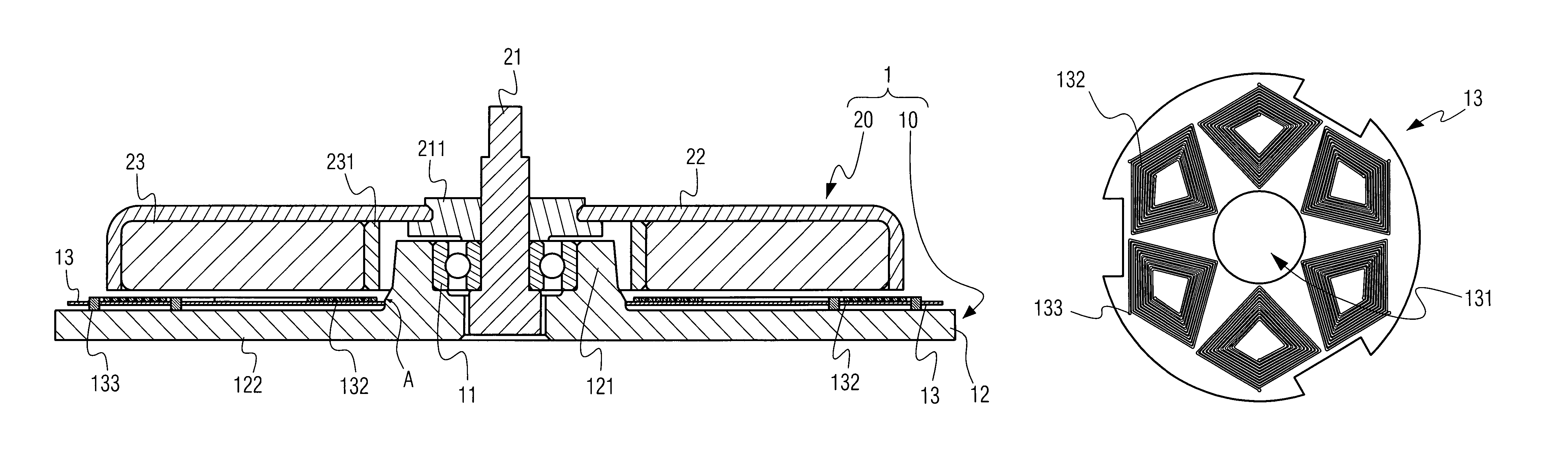
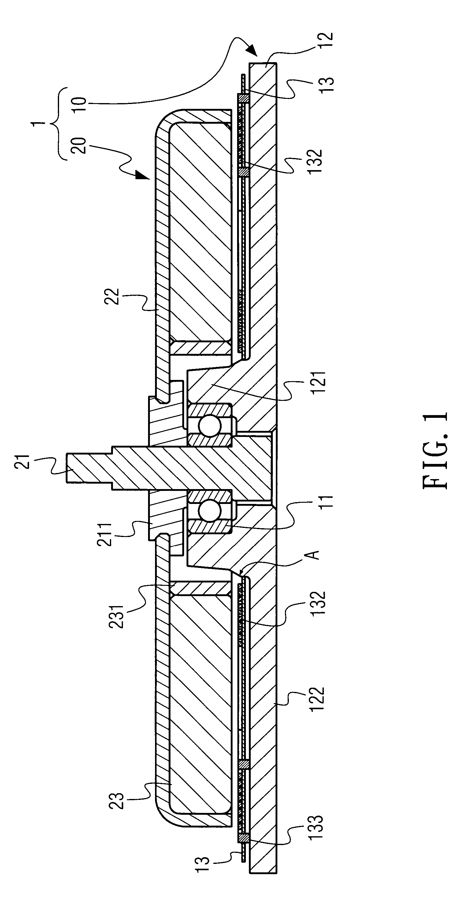
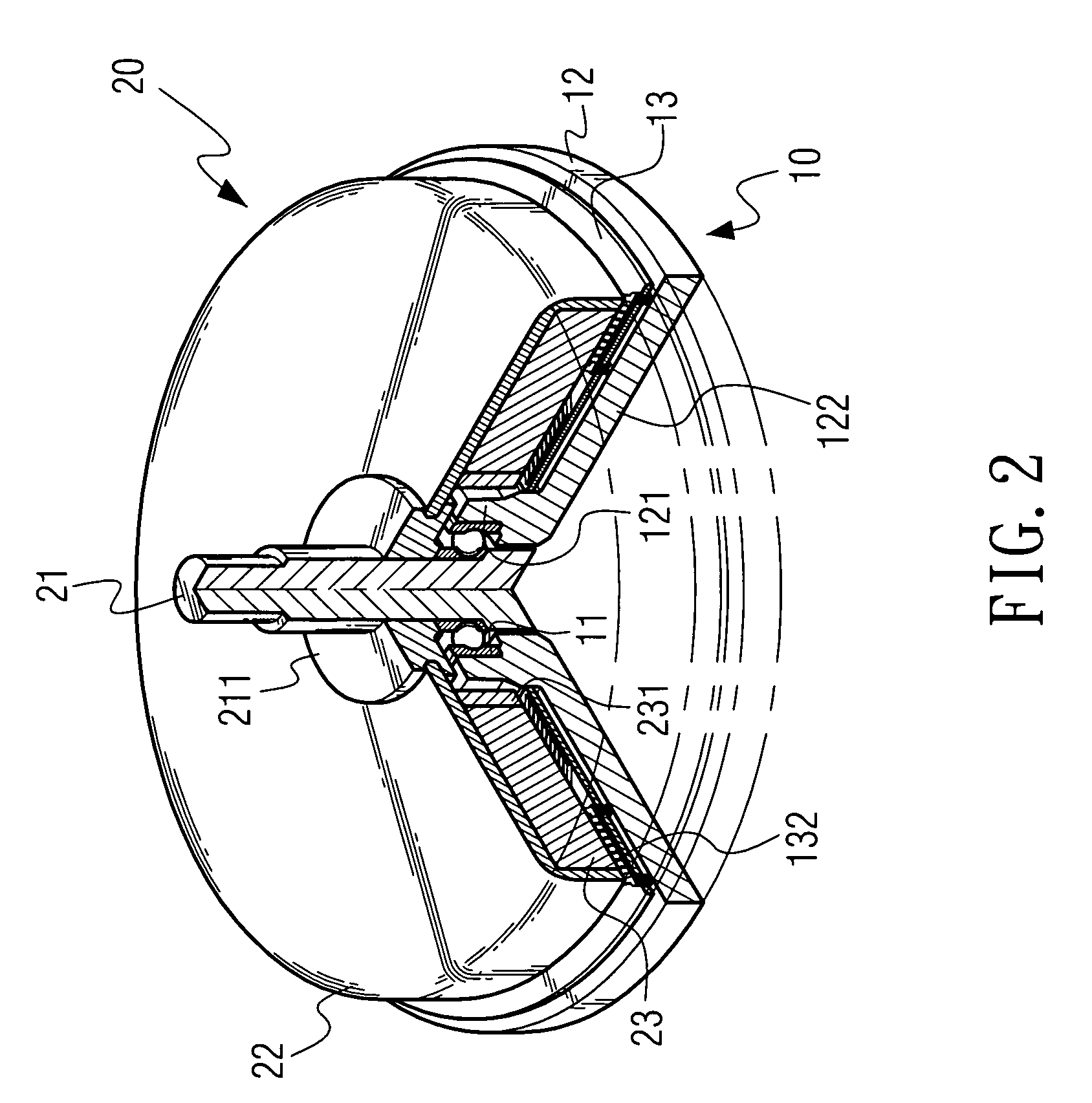
[0020]Referring to FIGS. 1 and 2, the invention relates to an ultra-thin motor structure. The ultra-thin motor structure 1 includes a stator assembly 10 and a rotator assembly 20. The stator assembly 10 includes at least one bearing 11 with a bore, a base 12, and a winding plate 13. Furthermore, the base 12 of the stator assembly 10 has a protruding portion 121 and a deck 122. The bearing 11 is disposed in the protruding portion 121 of the base 12, and the winding plate 13 is stacked on the deck 122 of the base 12. More specifically, a guide angle A is formed at the connection between the protruding portion 121 of the base 12 and the deck 122, and a hole 131 (as shown in FIG. 3) is formed at the center of the winding plate 13, so that the winding plated 13, when being stacked on the deck 122 of the base 12, is positioned and fixed by the guide angle A so as to be clamped at the guide angle A. Additionally, the rotator assembly 20 is disposed on the stator assembly 10. The rotator as...


PUM


Abstract

An ultra-thin motor structure including a stator assembly and a rotator assembly is provided. The stator assembly includes at least one bearing with a bore, a base, and a winding plate. The base has a protruding portion and a deck disposed in the protruding portion. The winding plate is stacked on the deck, and includes a plurality of coils formed by an electroforming process or etching process. Furthermore, the rotator assembly is disposed on the stator assembly, and includes a spindle, a top cover, and a permanent magnet ring. The spindle is fixed in the bore of the bearing, and the permanent magnet ring is disposed on the winding plate and supports the top cover thereon. Thereby, the ultra-thin motor structure can enhance the assembly and mass-production of the motor, and satisfy demands for thinning and performance of the motor.

Description

BACKGROUND OF THE INVENTION[0001]1. Field of Invention[0002]The present invention relates to a structure design of a motor, and more particularly to an ultra-thin motor structure capable of effectively thinning the motor and improving power density.[0003]2. Related Art[0004]The advent of the so-called information age is due, in most part, to the proliferation of the mass media and the internet, but the development of the spindle motor, which is most often used in Optical Disk Drives or hard disk drivers to store massive electronic data, also plays a key role.[0005]Nowadays, as compact and lightweight designs have become the mainstream of the market and even the norms of the industry, most electronic products have to be made smaller and smaller to meet consumers' insatiable demand for things slim and small. As a result, the thinning of components in such products is becoming increasingly important. The spindle motor is no exception to this trend. Manufacturers have been making every ...

Claims


Application Information

Patent Timeline
Patent Type & Authority Patents(United States)
IPC IPC(8): H02K3/26H02K5/173
CPCH02K5/1735H02K21/24H02K3/26Y10S310/06
Inventor TSAI, MING-CHINCHEN, CHIEN-JENHSU, LIANG-YITSAI, MI-CHING
Owner METAL INDS RES & DEV CENT
Why Eureka
Try Eureka