Lead frame, method of manufacturing a face-down terminal solid electrolytic capacitor using the lead frame, and face-down terminal solid electrolytic capacitor manufactured by the method

a solid electrolytic capacitor and lead frame technology, applied in the direction of fixed capacitor details, casings/cabinets/drawers, electrical equipment casings/cabinets/drawers, etc., can solve the problems of inability to achieve sufficient low values of esr and esl of the entire capacitor, disadvantageous structure of the electrode terminal, etc., to achieve excellent reliability, low value, and improved lead frame structure

Active Publication Date: 2009-06-02
TOKIN CORP
View PDF14 Cites 14 Cited by
  • Summary
  • Abstract
  • Description
  • Claims
  • Application Information

AI Technical Summary

Benefits of technology

[0006]It is therefore an object of this invention to provide a lead frame capable of reducing a current path distance between an anode and a cathode so as to achieve sufficiently low values of ESR and ESL of an entire capacitor.
[0022]With such a shape of the concave surface, cutting for separating a chip body from the lead frame is facilitated. Herein, the chip body represents a main body of the face-down terminal solid electrolytic capacitor, which is connected to the lead frame and subjected to cutting.
[0025]By providing the convex surface with the projecting portions or the recessed portions in this manner, the projecting portions or the recessed portions serve as anchors to the casing resin so that the fixing strength is enhanced.
[0028]By providing each of the anode terminal forming portion and the cathode terminal forming portion with the film containing at least one of Ag, Au, Cu, Pd, and Sn in this manner, the bonding force with a solder or the like at the interface increases.
[0029]With respect to a current path particularly in a high frequency band, a skin depth δ is given by δ=(ρ / πfμ)1 / 2, where ρ represents a resistivity, f, a frequency, and μ, a permeability. According to this equation, a surface current path of the depth of several tens of μm or less has an influence due to the skin effect in a high frequency band. Therefore, in order to reduce the ESL, it would be a best approach to adopt a structure plated with Au having a low resistivity ρ. Further, if the anode terminal and the cathode terminal in the thickness direction as part of the current path between the anode and the cathode are cut in order to arrange the shape, cutting is preferably carried out in the manner such that the plated surfaces remain at the concave surfaces of the electrode terminal forming portions (the anode terminal forming portion and the cathode terminal forming portion). Thus, the ESL can be reduced.
[0034]Also in the above-mentioned facedown terminal solid electrolytic capacitor, the structure of the lead frame is improved. Therefore, the current path between the anode and the cathode becomes short so that the ESR and the ESL of the entire capacitor have sufficiently low values. Therefore, excellent reliability is assured.

Problems solved by technology

However, the above-mentioned face-down terminal solid electrolytic capacitors are disadvantageous in electrode terminal structure.
Thus, it is not possible to achieve sufficiently low values of ESR and ESL of the entire capacitor.

Method used


Image

  • Lead frame, method of manufacturing a face-down terminal solid electrolytic capacitor using the lead frame, and face-down terminal solid electrolytic capacitor manufactured by the method
  • Lead frame, method of manufacturing a face-down terminal solid electrolytic capacitor using the lead frame, and face-down terminal solid electrolytic capacitor manufactured by the method
  • Lead frame, method of manufacturing a face-down terminal solid electrolytic capacitor using the lead frame, and face-down terminal solid electrolytic capacitor manufactured by the method

Examples


Embodiment Construction

[0046]In order to facilitate understanding of this invention, description will first be made of a basic structure of a face-down terminal solid electrolytic capacitor as a background technique preceding this invention. Face-down terminal solid electrolytic capacitors of this type have been suggested by the present assignee in Japanese Unexamined Patent Application Publication (JP-A) No. 2005-197457 (corresp. to U.S. Pat. No. 6,975,503 B2), Japanese Unexamined Patent Application Publication (JP-A) No. 2006-190965 (corresp. to US 2006 / 0126273 A1), and so on.

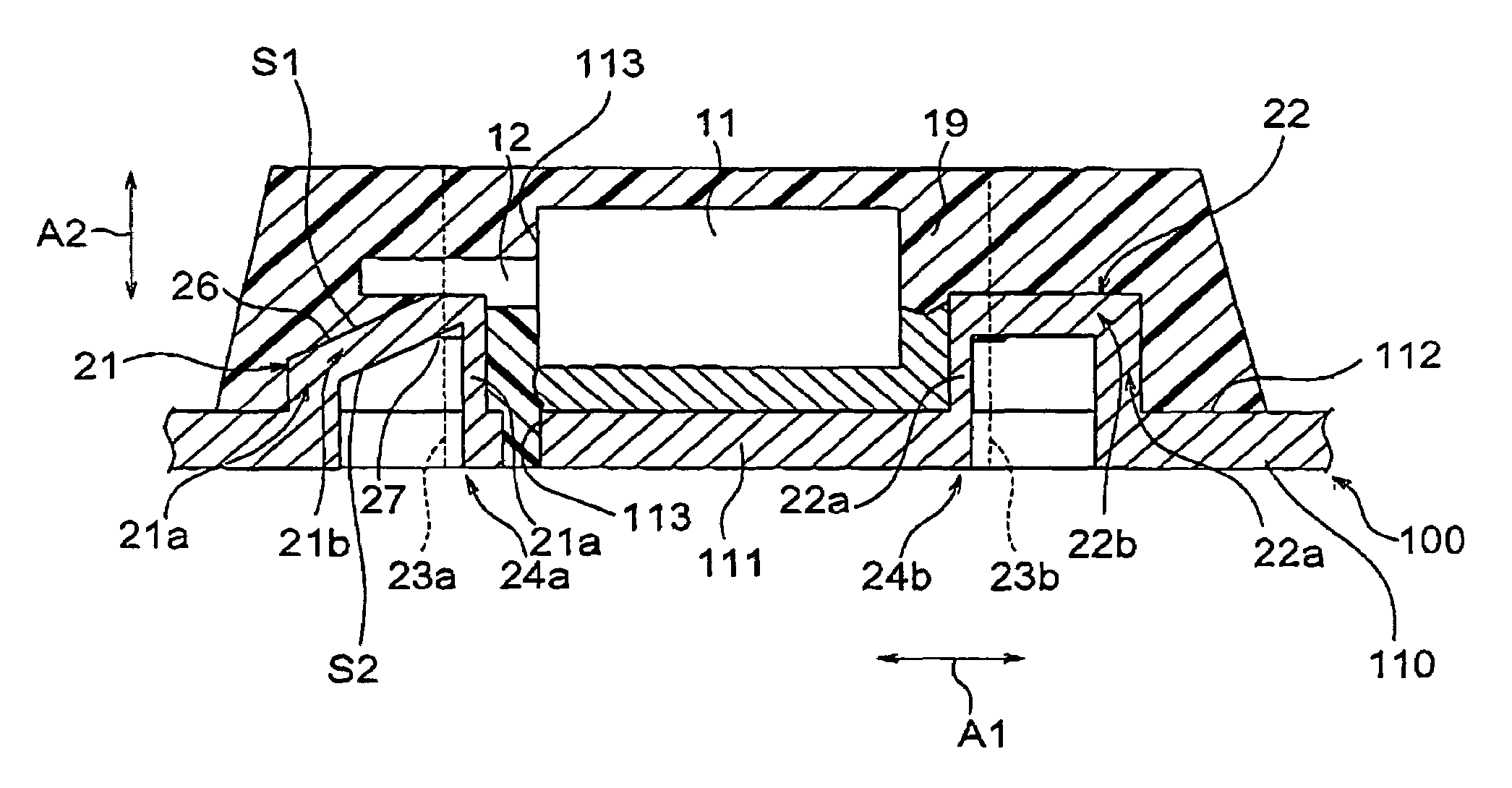
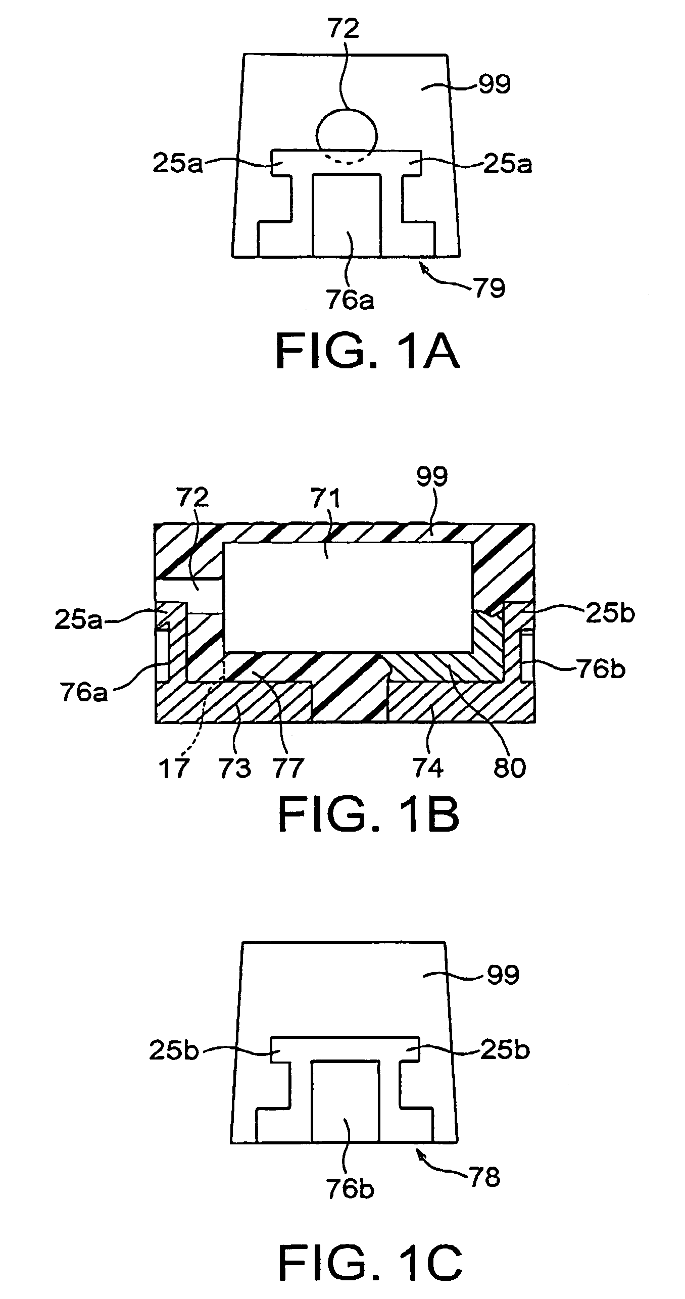
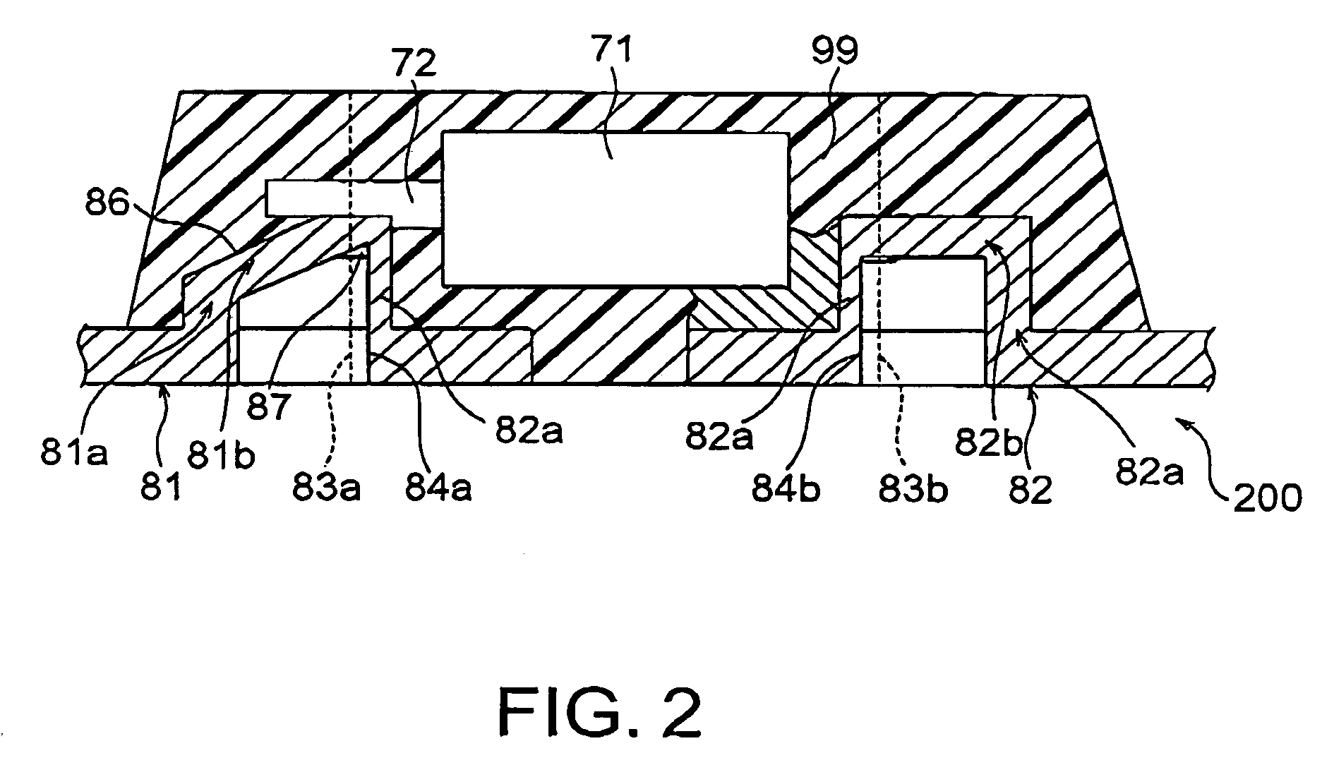
[0047]Referring to FIGS. 1A to 1C, the face-down terminal solid electrolytic capacitor comprises a capacitor element 71 having a dielectric layer, an electrolyte layer, and a cathode layer successively formed on a surface of a porous sintered body made of a valve-action metal, and an anode lead 72 drawn out from the capacitor element 71. A lead frame 200 has an anode terminal forming portion 81 and a cathode terminal forming portio...


PUM

PropertyMeasurementUnit
shapeaaaaaaaaaa
insulatingaaaaaaaaaa
sizeaaaaaaaaaa

Abstract

In a lead frame for use in fabricating a face-down terminal solid electrolytic capacitor having a capacitor element an anode terminal, and a cathode terminal, a frame body has a connecting portion for being connected to the capacitor element. The connecting portion extends from a cathode terminal forming portion in a first direction to a position near an anode terminal forming portion. The anode terminal forming portion is connected to the frame body and used for forming the anode terminal. The cathode terminal forming portion is connected to the frame body and used for forming the cathode terminal. The anode terminal forming and the cathode terminal forming portions are spaced to each other in the first direction on a principal surface of the frame body.

Description

BACKGROUND OF THE INVENTION[0001]This invention mainly relates to a lead frame for use in fabrication of a solid electrolytic capacitor of a facedown terminal type (hereinafter referred to as a “face-down terminal solid electrolytic capacitor”) having electrodes directly drawn out or led out to a board mount side and further relates to a method of manufacturing a face-down terminal solid electrolytic capacitor using the lead frame and a face-down terminal solid electrolytic capacitor manufactured by the method.[0002]Solid electrolytic capacitors using tantalum, niobium, or the like as a valve-action metal are small in size, large in capacitance, and excellent in frequency characteristic and, therefore, have been widely used, for example, in decoupling circuits and power supply circuits of CPUS. With the recent development of portable electronic devices, commercialization is increasingly made of a face-down terminal solid electrolytic capacitor having electrodes directly drawn out to...

Claims


Application Information

Patent Timeline
Patent Type & Authority Patents(United States)
IPC IPC(8): H01G9/00
CPCH01G2/065H01G9/012H01G9/10Y10T29/417Y10T29/41Y10T156/1052
Inventor ISHIJIMA, MASAMI
Owner TOKIN CORP
Why Eureka
Try Eureka