
Air-conditioned storage cupboard

a technology of air-conditioning storage cabinets and storage cabinets, which is applied in the direction of material testing goods, biochemistry equipment and processes, biochemistry apparatus, etc., can solve the problems of inability to maintain the desired temperature, the value of the objects stored in the storage system is extremely high, and the cost of the whole system can be a multiple of the cost of the whole system,

Active Publication Date: 2009-06-09
LICONIC
View PDF60 Cites 8 Cited by
  • Summary
  • Abstract
  • Description
  • Claims
  • Application Information

AI Technical Summary

Benefits of technology

[0018]In another aspect of the invention, a heating device and a cooling device are provided in the climate controlled cabinet. In this manner, an improved independence of the climate temperature from the environmental temperature and heat generation of the handling device is achieved. In particular, a method for operating a climate controlled cabinet is provided where at least part of the heat generated by the handling device is actively withdrawn by means of the cooling device even if the desired temperature is higher than the environmental temperature.
[0026]Another aspect of the invention relates to climate controlled cabinets in the climate controlled chamber of which at least one rotatable carousel is provided, in which a plurality of storage positions for receiving the objects to be stored is arranged in star shaped manner around an axis of the carousel. The handling device has a scoop, which can be displaced horizontally and vertically and be pivoted about a vertical axis. For compensating the weight during vertical movements of the scoop, a counter weight is provided in the carousel axis and attached via a weight deflection. This allows a good exploitation of the space in the carousel axis.

Problems solved by technology

The value of the objects stored in the storage systems is extremely high and can be a multiple of the costs of the whole system.
Because of the high insulating values of the cabinet insulation, even small heat sources can lead to substantial inherent warming of the climate controlled chamber and to undesired condensation at the walls, or they even make it impossible to maintain the desired temperature.
The storage density per laboratory area in this system is, however, small.
Also disadvantageous is the design of the storage towers, which does not allow a secure manual loading and unloading of the objects to be stored, does not have the mechanical precision required for automatic access and can even represent a danger of injury at the sharp edges.
Such embodiments can, basically, be constructed to be as large as required, but they have the decisive disadvantage that the objects can only be loaded or unloaded manually in complicated manner and at a large risk of misidentification.
Such designs are only suited for a small number of storage towers and are therefore not suited for being used in larger systems.
This arrangement is not suited for a large number of accesses.
If the substances have to remain within the cabinet for a long time, the transport system should, however, be maintenance free because maintenance work causes a loss of climatization.
A further disadvantage of the device according to this publication is that the arrangement of the scoop drive degrades the usage of available space if the scoop mechanism is used in connection with a carousel in a climate controlled cabinet because the horizontal arrangement of the scoop drive requires a large lateral displacement for the cog rail.
When access occurs very frequent and at short time intervals, however, undesired climatic fluctuations occur also for these devices.
Objects that are removed from the climate controlled chamber require, furthermore, substantial time until they reach the desired storage temperature again.
This disadvantage is particularly disturbing because, in storage applications, the same object has often to be removed from the climate controlled chamber and fed back repetitively in short temporal intervals.
Furthermore, the known devices cannot satisfy the desire for high access times even for large access paths while being maintenance-free at the same time.
First, it suffers much more under accesses than, for example, temperature, and, second, it determines the evaporation limited storage duration of the objects in the climate controlled chamber.
Adding a cooling device is, in the concerned applications, not possible without further measures because cooling is problematic when the humidity is high.
This would, however, cause a loss of the homogenization of the temperature that was achieved by the cavity.
Furthermore, foaming would require complicated scaffolding for receiving the forces generated by the foaming process.
This would make maintenance or repair work for components arranged around the climate controlled space impossible or at least difficult.
Also, building a scaffolding is expensive.
For the small product life times, small numbers of units and large product diversity in the market of automatic incubators, such investments could not be amortised.
Commercial standard devices do not have the desired dimensions for the climate controlled chamber.
Also, the usual cooling used in such devices, where a cooling member is arranged in the climate controlled chamber or in a extended part of the climate controlled chamber, would lead to a drying out of the climate controlled chamber.
This has the disadvantage that comparatively large temperature fluctuations are observed.
In addition, it is disadvantageous that vibrations occur when switching on and off, which can affect the precision of the handling device.
Due to the heat generation of the handling device, the quality of the climate that can be achieved is impaired.
Devices of the above type are used in complicated and costly systems, into which they have to be integrated with a great effort.
Their limited usability is therefore especially noticeable as a disadvantage.
This substantially reduces the usability of sensors, and sensors must be used that have disadvantageous properties, such as low effective signals and drift.
Finally, the known devices are complicated to integrate into a host system because many functions must be implemented by the integrator and a plurality of interfaces are necessary, or certain functions cannot be carried out by the host system at all or certain values are not accessible for the same.

Method used


Image

  • Air-conditioned storage cupboard
  • Air-conditioned storage cupboard
  • Air-conditioned storage cupboard

Examples


Embodiment Construction

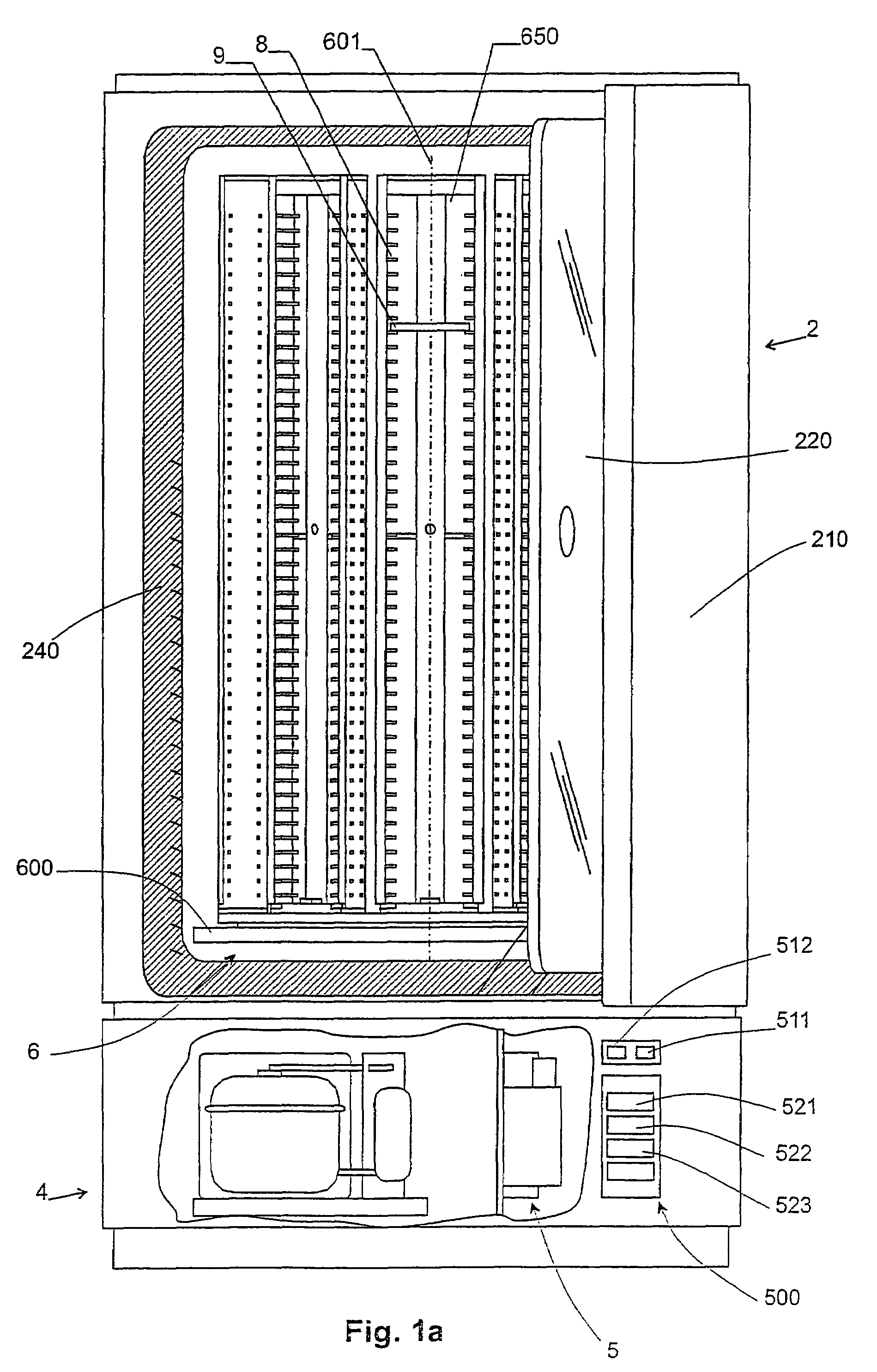
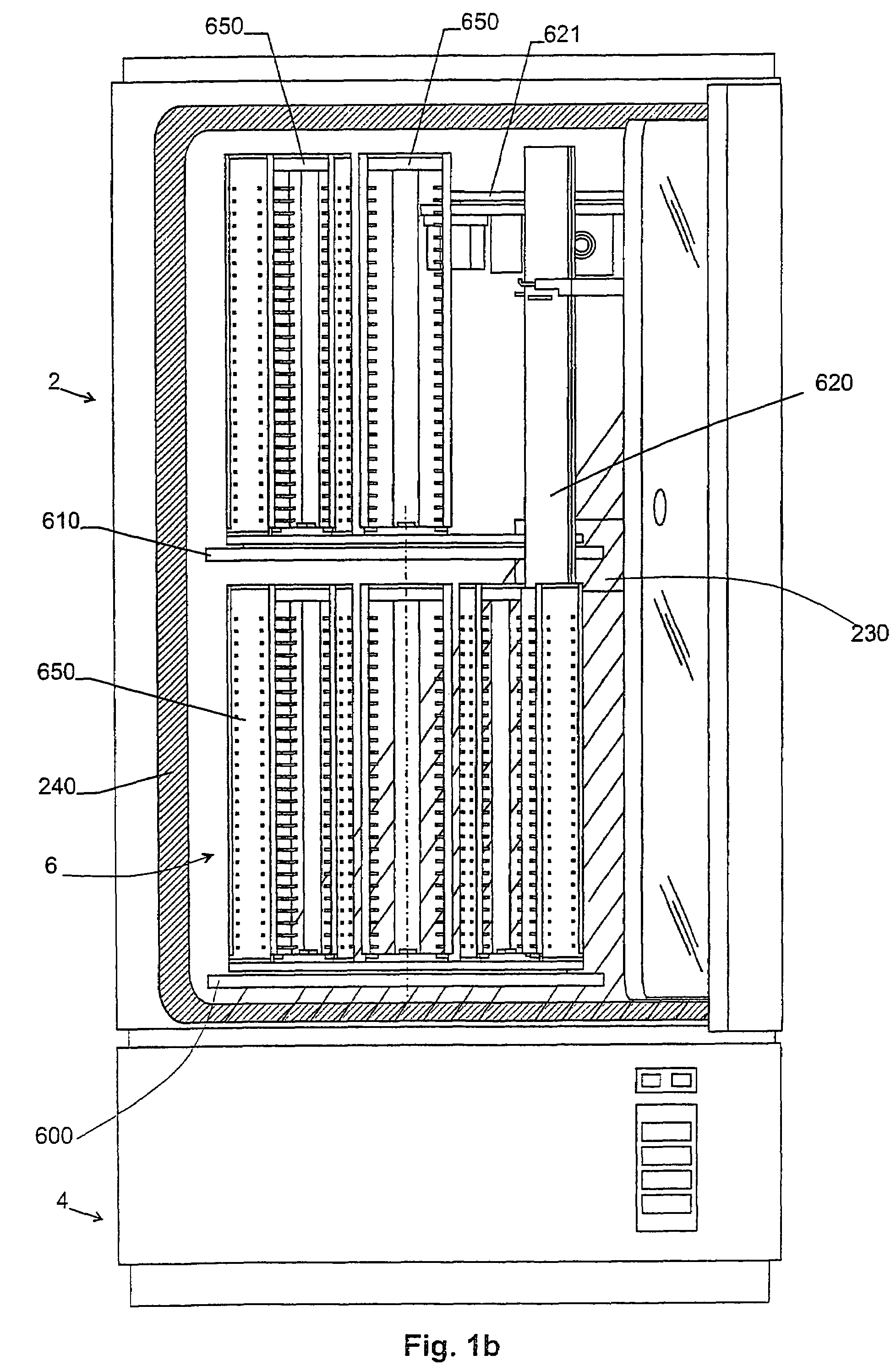
[0045]Common to all embodiments of the climate controlled cabinet shown here the climate controlled cabinet comprises a climate controlled chamber 2 and a control chamber 4.

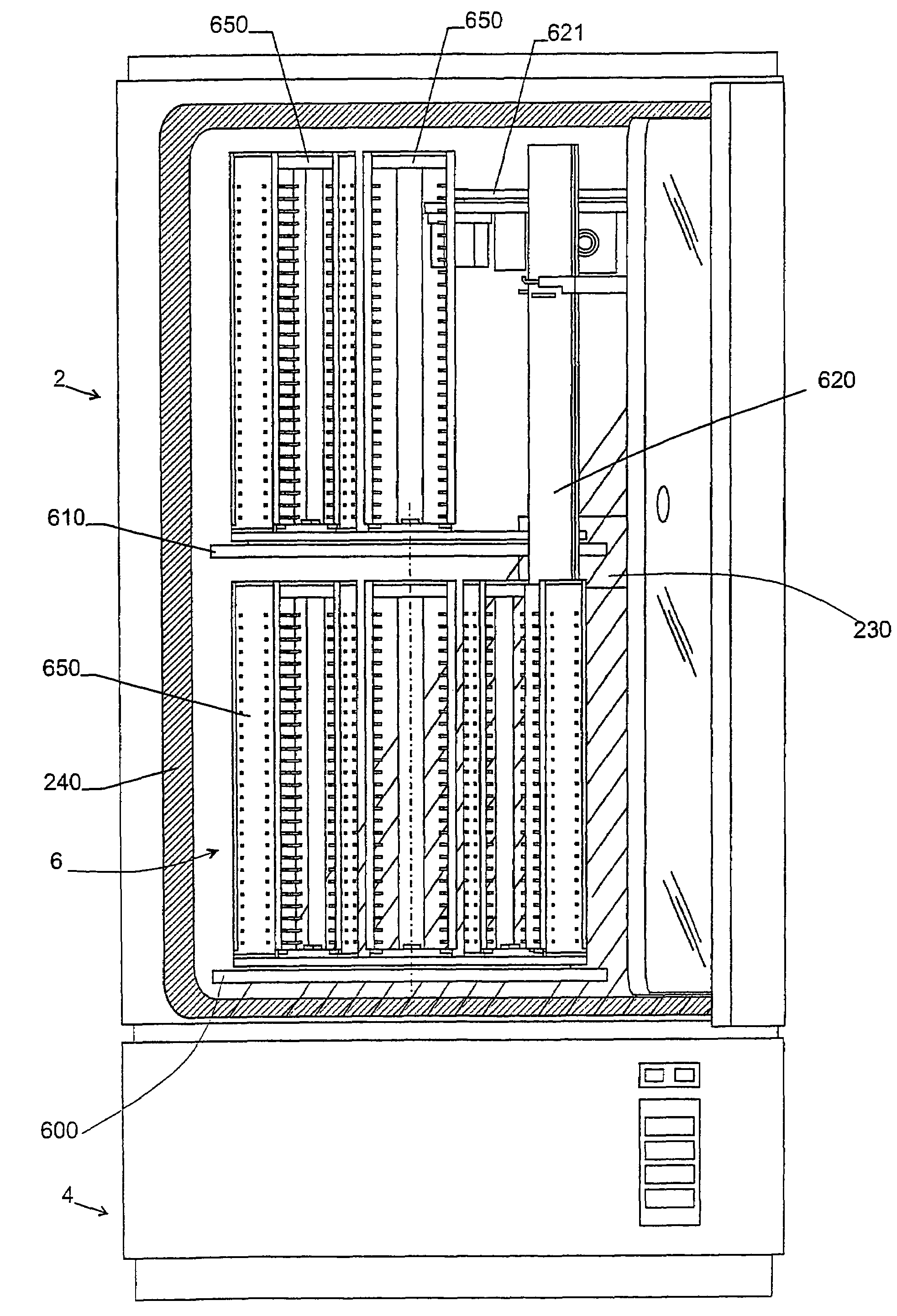
[0046]A plurality of storage-positions 8 for the objects 9 to be stored are provided in climate controlled chamber 2. It has an outer and an inner user door 210 and 220, respectively, at the front side and an auxiliary door 15 at the back side. The user doors 210, 220 serve for manual access to the interior of climate controlled chamber 2. Outer user door 210 is thermally insulated and non-transparent, the inner user door has a transparent, thermally insulated double glazing. Within climate controlled chamber 2, a handling device 620 is arranged for automatically transporting the objects between the storage positions and a transfer position outside the climate controlled cabinet, for which purpose auxiliary door 15 is used.

[0047]A controller as well as various apparatus 5 for generating heat, cold and / or controll...


PUM

PropertyMeasurementUnit
temperaturesaaaaaaaaaa
temperatureaaaaaaaaaa

Abstract

The invention relates to a climate controlled cabinet with a common controller (300) for climate and handling of the goods to be stored. By means of this design the construction and operation can be simplified and the climate control can be improved. To further improve the climate control, a heating as well as a cooling device (242, 244) are provided such that heat generated by the handling device (620) can be dissipated when necessary.

Description

CROSS REFERENCE TO RELATED APPLICATIONS[0001]This application claims the priority of Swiss patent application 0136 / 01, filed 26 Jan. 2001, the disclosure of which is incorporated herein by reference in its entirety.BACKGROUND OF THE INVENTION[0002]The invention relates to a climate controlled cabinet and a method for operating such a cabinet according to the preamble of the independent claims.[0003]In substance research and microbiology the used objects must be stored under exactly predefined climatic conditions. The temperatures of the storage range typically approximately from the freezing point of water up to room temperature. The objects usually consist of containers for several liquid probes. The volumes of the probes are becoming smaller and smaller, and the logistics of the objects are increasingly carried out automatically. The capacity of the storage systems increases and, often, several such storage systems are used within one system. The value of the objects stored in the...

Claims


Application Information

Patent Timeline
Patent Type & Authority Patents(United States)
IPC IPC(8): B01L9/00C12M1/00
CPCC12M23/50C12M41/14G01N35/04B01L1/02B01L9/523G01N35/00732G01N2035/00356G01N35/025
Inventor MALIN, COSMAS G.
Owner LICONIC
Learn More