

Device for operating gas in vacuum or low-pressure environment and for observation of the operation
a vacuum or low-pressure environment and gas-operating technology, applied in the field of gasiform substance operation, can solve the problems of gas leakage into the vacuum zone, aberration and resolution loss, complicated disassembly and assembly of electron microscopes, etc., and achieve the effect of convenient operation, convenient assembly and convenient assembly
- Summary
- Abstract
- Description
- Claims
- Application Information
AI Technical Summary
Benefits of technology
Problems solved by technology
Method used
Image


Examples
first embodiment
[0052]Referring to FIG. 5, a device 50 for operating gas in the vacuum or low-pressure environment and for observation of the operation, constructed according to a second preferred embodiment of the present invention, is similar to the first embodiment, but has differences as follows.
[0053]The housing 11′ is partitioned off additionally into an upper buffer chamber 181′ and a lower buffer chamber 181′, which are located respectively above and below the two buffer chambers 18′. Additional pumping ports are formed in the housing 11′, there being now the two pumping ports 116′ as described in the previous embodiment, and two additional pumping ports 117′, wherein the two buffer chambers 18′ correspond respectively to the two pumping ports 116′, and the upper and lower buffer chambers 181′ correspond respectively to the two pumping ports 117′. Two buffer apertures 144′ are formed respectively in the two spacers 14′ located respectively between the upper buffer chamber 181′ and the buffe...
fifth embodiment
[0068]Referring to FIGS. 12 and 13, a device b10 for operating gas in the vacuum or low-pressure environment and for observation of the operation, constructed according to a sixth preferred embodiment of the present invention, is similar to the fifth embodiment, having difference recited below.
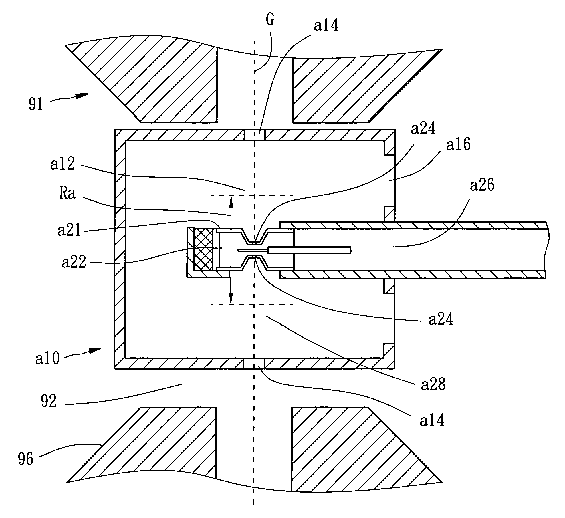
[0069]The spacer b21 is separable from the housing b11, and namely, the gas chamber b22 enclosed by the spacer b21 is separable from the housing b11 and the buffer chamber b12. In this embodiment, the spacer b21 is formed on a specimen holder b25 and the gas chamber b22 is formed between the spacer b21 and the specimen holder b25. At least one sealing piece b29, like O-ring, is mounted to seal among the specimen holder b25, the spacer b21, and the housing b11.
sixth embodiment
[0070]While the sixth embodiment is in operation, the spacer b21 is placed into the housing b11 and the sealing piece b29 is located among the specimen holder b25, the spacer b21, and the housing b11 for the sealing potency. The rest of the operation, including gas evacuation and infusion, is the same as the aforementioned embodiment, such that no further description is necessary.
[0071]Referring to FIGS. 14 and 15, a device c10 for operating gas in the vacuum or low-pressure environment and for observation of the operation, constructed according to a seventh preferred embodiment of the present invention, is similar to the sixth embodiment, having difference recited below.
[0072]In addition to the gas chamber c22 enclosed by the spacer c21 in the specimen holder c25, the housing c11 further includes a plurality of spacers c17 mounted therein for partitioning the interior space thereof additionally into an inner buffer chamber c18 formed inside the buffer chamber c12. Two buffer apertu...
PUM
 Abstract
Description
Claims
Application Information