Fan motor control method and device thereof

a technology of control method and control device, which is applied in the direction of electric controller, dynamo-electric converter control, instruments, etc., can solve the problems of increasing frequency, increasing voltage and noise, and improving stability, so as to improve stability, increase frequency, and increase voltage and noise

Active Publication Date: 2009-06-09
DELTA ELECTRONICS INC
View PDF14 Cites 6 Cited by
  • Summary
  • Abstract
  • Description
  • Claims
  • Application Information

AI Technical Summary

Benefits of technology

[0008]In view of the foregoing, the invention is to provide a fan motor control method and device thereof, which can produce more than 23 KHz of high-frequency drive signal by the control device in order to drive the fan motor. This results in improving the drawbacks of stability, higher voltage and the noises by the increased frequency.

Problems solved by technology

This results in improving the drawbacks of stability, higher voltage and the noises by the increased frequency.

Method used


Image

  • Fan motor control method and device thereof
  • Fan motor control method and device thereof
  • Fan motor control method and device thereof

Examples


Embodiment Construction

[0018]The following description is of the best-contemplated mode of carrying out the invention. This description is made for the purpose of illustrating the general principles of the invention and should not be taken in a limiting sense. The scope of the invention is best determined by reference to the appended claims.

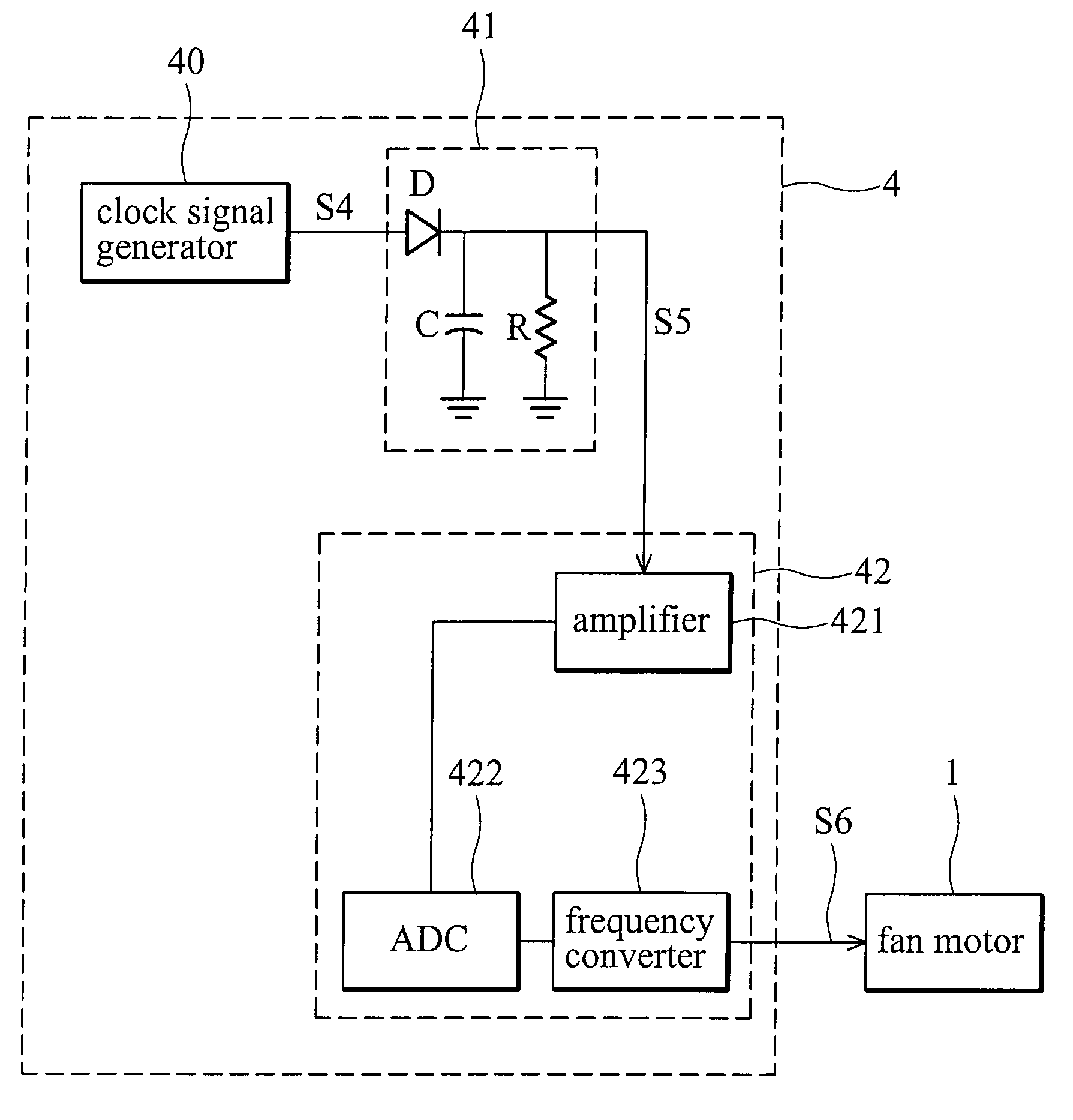
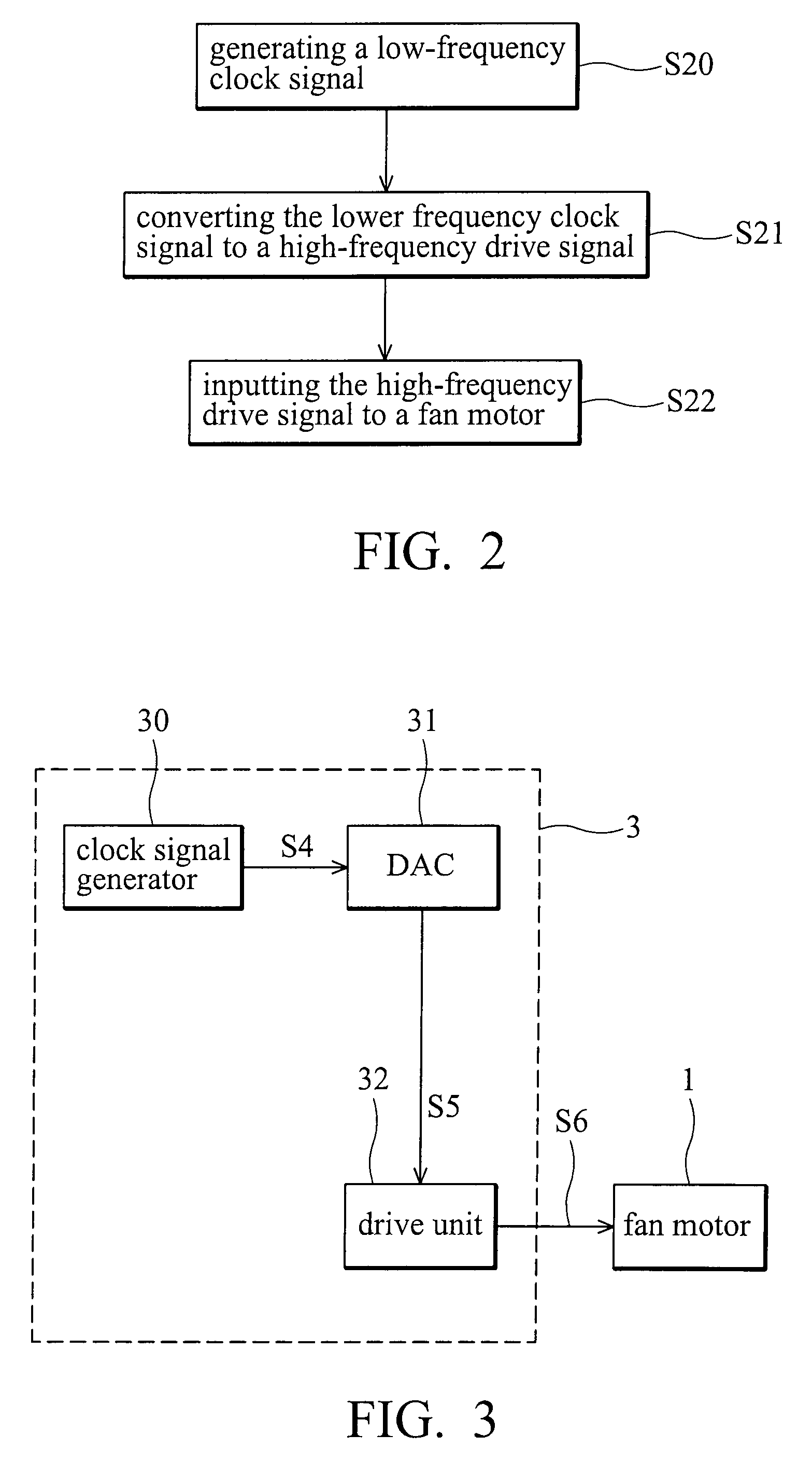
[0019]As shown in the FIG. 2, a motor control method according to the invention includes a low-frequency clock signal is generated (step S20), and a frequency of the low-frequency clock signal is less than 23 KHz. The low-frequency clock signal is converted to a high-frequency drive signal (step S21), and the frequency of the high-frequency drive signal is higher than 23 KHz. The high-frequency drive signal is input to the fan motor to drive the fan motor or adjust the rotation speed of the fan motor (step S22).

[0020]The low-frequency clock signal or the high-frequency drive signal can be a pulse width modulation (PWM) signal. The preferred frequency of the high-freque...


PUM


Abstract

A fan motor control device comprises a clock signal generator and a drive unit. The clock signal generator generates a low-frequency clock signal. A frequency of low-frequency clock signal is less than 23 KHz. The drive unit converts the low-frequency clock signal to a high-frequency drive signal and outputs the high-frequency drive signal to drive the fan motor. A frequency of the high-frequency drive signal is higher than 23 KHz.

Description

BACKGROUND OF THE INVENTION[0001]1. Field of the Invention[0002]The invention relates to a fan motor control method, and in particular to a fan motor control device.[0003]2. Description of the Related Art[0004]Electronic systems generate heat based on the amount of data they process. Because some electronic systems provide fast and continuous operations, heat dissipation devices for these electronic systems are more important. Various heat dissipation products are provided for users, and fan systems are currently popular among the most.[0005]FIG. 1 depicts a conventional fan system. A fan system comprises a fan motor 1 and a control device 2 controlling the fan motor 1. The control device 2 is electrically connected to the fan motor 1 to control the fan motor 1.[0006]The control device 2 comprises a clock signal generator 20, a digital-to-analog converter (DAC) 21, and a drive unit 22. The clock signal generator 20 generates a low-frequency clock signal S1. The low-frequency clock s...

Claims


Application Information

Patent Timeline
Patent Type & Authority Patents(United States)
IPC IPC(8): H02K29/06H02P1/00H02P29/00
CPCH02P7/285
Inventor WU, CHIA-FENGHUANG, YUEH-LUNGTSAI, MING-SHIHUANG, WEN-SHI
Owner DELTA ELECTRONICS INC
Why Eureka
Try Eureka