Fiber optic cabling for multi-dwelling unit (MDU) and commercial building deployments

a fiber optic cabling and multi-dwelling unit technology, applied in the field of system and technique for deploying fiber optic cabling, can solve the problems of inconvenient widespread deployment of fiber optic networks, large drop boxes currently available, and difficult time-consuming for single workers to install cable drop boxes at subscriber premises

Inactive Publication Date: 2009-06-09
COMMSCOPE TECH LLC
View PDF18 Cites 125 Cited by
  • Summary
  • Abstract
  • Description
  • Claims
  • Application Information

AI Technical Summary

Problems solved by technology

Installation of the known cable drop boxes by a single worker at a subscriber premises can be difficult and time consuming, however.
Accordingly, the currently available drop boxes are relatively large, and are not suitable for widespread deployment of fiber optic networks at multi-dwelling units or other buildings without significant expenditures of time and labor.
The portion of that individual fiber that remains in the distribution cable is then left unused and becomes “dead”, however.
Accordingly, when multiple midspan access points are required for drops, half of the fiber in the distribution cable may be left unused or is wasted.
Another problem arises when bringing a fiber optic network distribution system to a multi-dwelling residence or office building.
Thus, it may be difficult if not impossible to access the tethers on a fiber optic distribution cable once the cable is placed in the riser shaft of an existing building.

Method used


Image

  • Fiber optic cabling for multi-dwelling unit (MDU) and commercial building deployments
  • Fiber optic cabling for multi-dwelling unit (MDU) and commercial building deployments
  • Fiber optic cabling for multi-dwelling unit (MDU) and commercial building deployments

Examples


first embodiment

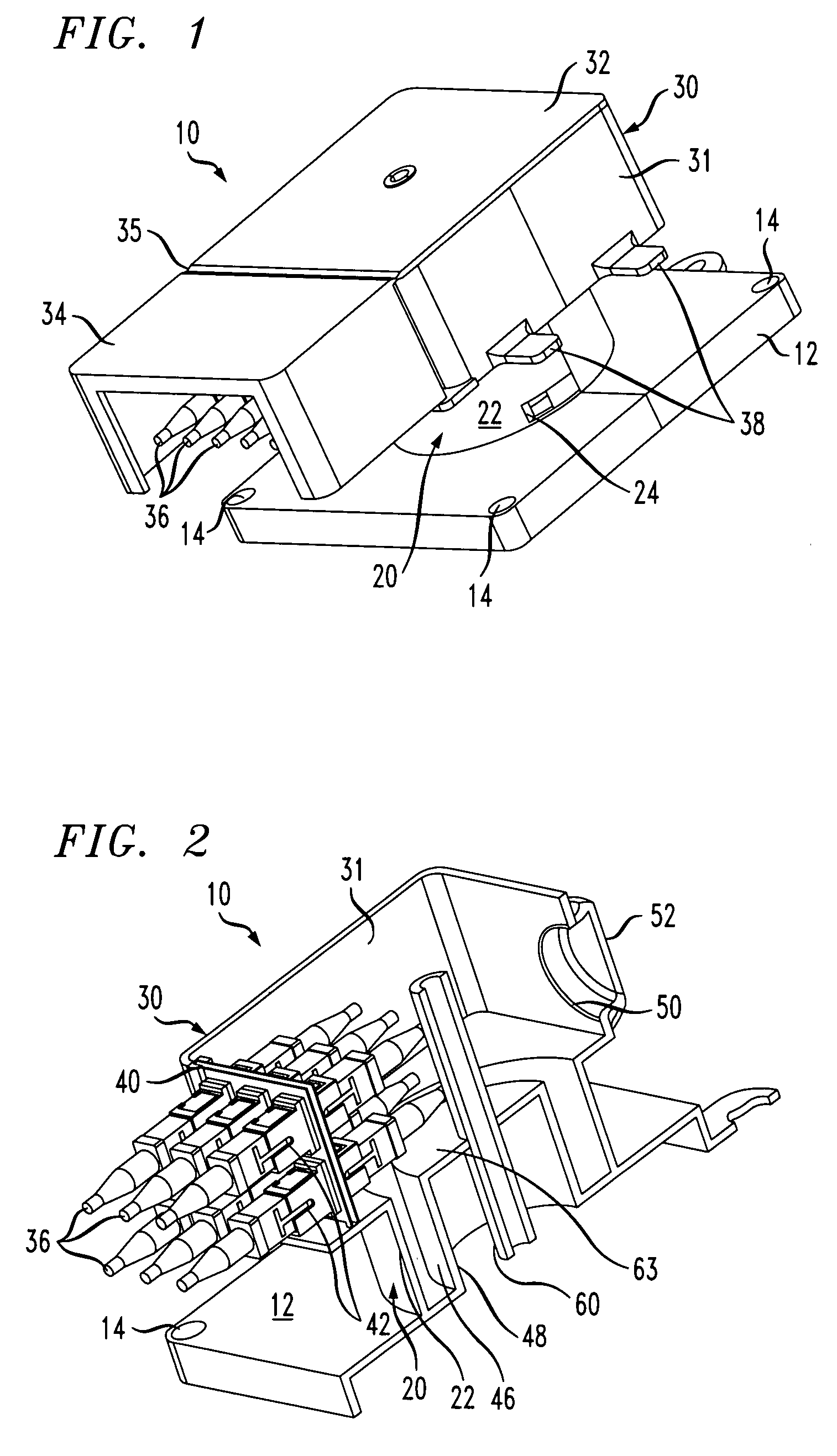
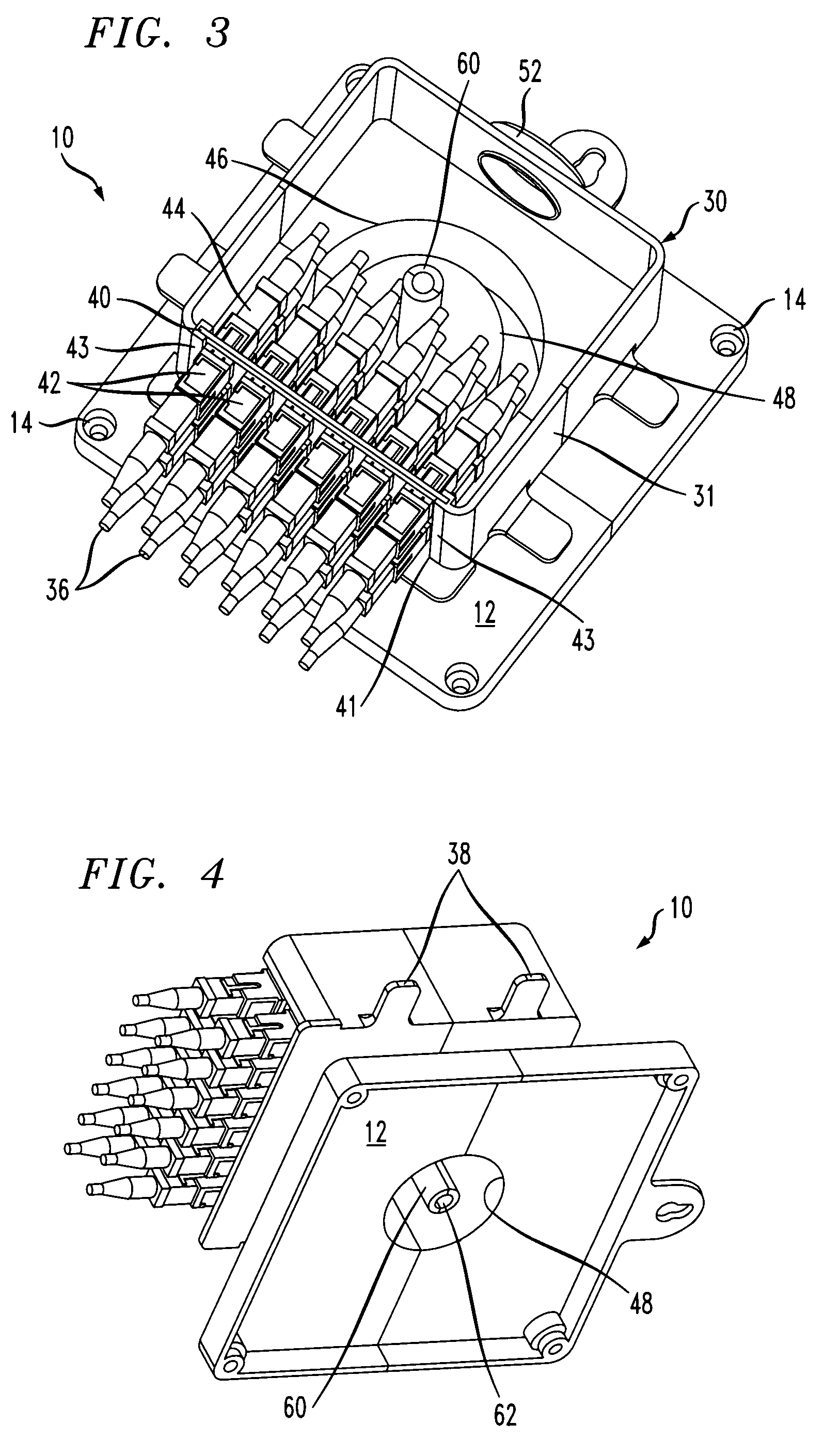
[0028]FIG. 1 shows optical fiber and cable management apparatus in the form of a cable drop box 10, according to the invention. The box 10 may be constructed of sheet metal, and / or plastics materials such as, without limitation, ABS or polycarbonate. Moisture proof seals, gaskets and the like may also be provided on or within the box 10 in a known manner if the box will be mounted outdoors at a subscriber premises. The box 10 has a base 12 which, in the disclosed embodiment, is generally square and measures, e.g., about 6.25 inches (158.75 mm) long on each side with mounting holes 14 formed at each corner of the base.

[0029]The box 10 also has a drum region 20 that extends axially upward from a central portion of the base 12. The drum region 20 includes an outer cylindrical wall 22 the outside periphery of which is partially visible in FIG. 1. The outside diameter of the wall 22 is sufficient to allow a length of a fiber optic cable (not shown) to be wound on the drum wall 22 for sto...

second embodiment

[0036]FIGS. 5 to 7 show a fiber-optic cable drop box 200 according to the invention. Components of the box 200 that are identical or similar to those of the box 10 of FIGS. 1 to 4, have corresponding reference numerals increased by 200.

[0037]The box 200 has a single piece cover lid 232 with an integrated hinge 235 for a connector guard or cover 234. Further, a side wall 231 of an interface compartment 230 has a continuous circular disk flange 204 that extends radially outward beneath the compartment 230, parallel to a base 212 of the box. The flange 204 and the base 212 together serve to confine a length of fiber optic cable wound on the outer cylindrical wall 222, within the region between the flange 204 and the base 212. As with the box 10 of FIGS. 1 to 4, an inside end portion of the cable is guided by a strain relief device 224 to enter an annular fiber routing region 246 inside the box 200, over a substantially straight path tangential to the circumference of the wall 222 at th...

third embodiment

[0043]FIGS. 10 to 12 show a fiber optic cable drop box 300 according to the invention. Components of the box 300 that are identical or similar to those of the box 10 of FIGS. 1 to 4, have corresponding reference numerals increased by 300. The box 300 features an integral splice compartment 308 in its base 312, a connector parking area 313, and a number of security latch holes 315.

Splice Compartment 308

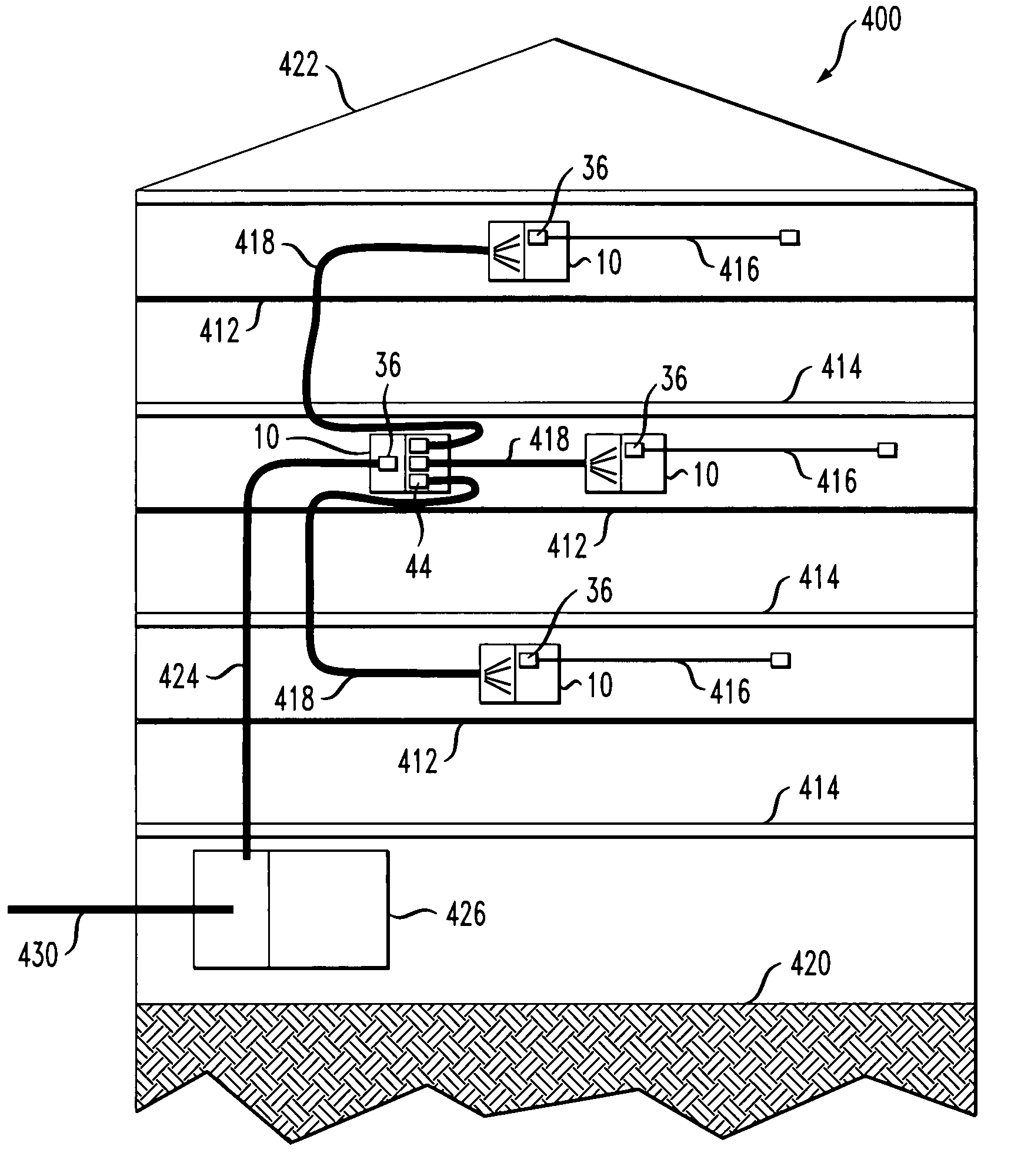
[0044]Typical MDU drop box installations have single fiber breakouts that egress from the box, wherein each breakout is associated with a corresponding living unit of the premises where the box is installed. Single fiber cables from each living unit are often routed to a drop box without a terminating connector. The bare ends of these cables can be terminated at the drop box in various ways. For example, single ended fiber pigtails can be spliced within the drop box so that splice sleeves are housed in a common space. This requires a chamber or compartment to house the splice in order ...


PUM


Abstract

A network provider cable is routed to a splitter box in a multi-dwelling unit or commercial building where the cable fibers are terminated. One or more riser cables, each terminated at one end at the splitter box, are routed through a building shaft. Each riser cable contains fibers associated with units located on a certain set of one or more floors of the building. The other end of each riser cable is terminated at an aggregation box associated with the floors of the set. A feeder cable is routed between the aggregation box and each floor of the set, or a corresponding floor area of one floor. A drop box is provided for each floor or floor area for terminating the corresponding feeder cable. Drop cables are routed between the drop box and units on the floor or in the floor area to be served.

Description

CROSS REFERENCE TO RELATED APPLICATIONS[0001]The present application claims priority under 35 U.S.C. §119(e) of U.S. Provisional Patent Application No. 60 / 880,169, filed Jan. 13, 2007, and entitled “Multidwelling Unit (MDU) Drop Box for Fiber Optic Cables”. Further, this application is a continuation-in-part (CIP) of U.S. Non-Provisional patent application Ser. No. 11 / 728,785 filed Mar. 27, 2007, now U.S. Pat. No. 7,400,814 and entitled “Wall-Mountable Optical Fiber and Cable Management Apparatus”.BACKGROUND OF THE INVENTION[0002]1. Field of the Invention[0003]The present invention concerns a system and technique for deploying fiber optic cabling for users in multi-dwelling unit (MDU) premises and commercial office buildings.[0004]2. Discussion of the Known Art[0005]The deployment of fiber optic networks at multi-dwelling units (MDUs) and other subscriber premises, requires the use of so-called cable drop boxes which are constructed for mounting on walls or other structures at the p...

Claims


Application Information

Patent Timeline
Patent Type & Authority Patents(United States)
IPC IPC(8): G02B6/00
CPCG02B6/4441G02B6/4466G02B6/475
Inventor HENDRICKSON, DANIELWEIMANN, PETER A.ZHANG, HONGBO
Owner COMMSCOPE TECH LLC
Why Eureka
Try Eureka