Face milling insert

a face-milling and insert technology, applied in shaping cutters, manufacturing tools, transportation and packaging, etc., can solve the problems of large stress on the edge piece that is torn loose laterally, blanks having to be discarded, and damage of this type, so as to improve the quality of face-milling and ensure the quality of the surface. good, long-lasting

Active Publication Date: 2009-06-16
SANDVIK INTELLECTUAL PROPERTY AB
View PDF8 Cites 39 Cited by
  • Summary
  • Abstract
  • Description
  • Claims
  • Application Information

AI Technical Summary

Benefits of technology

[0008]The present invention aims at obviating the above-mentioned shortcomings of previously known face-milling inserts, and at providing an improved face-milling insert. Therefore, a primary object of the invention is to provide a face-milling insert that does not give rise to burr formation in the machining of blanks of CGI. An additional object is to provide a face-milling insert that provides a good surface finish of the generated surface, and that furthermore has a long service life and ensures efficient chip removal.

Problems solved by technology

However, such milling inserts involved problems originating in the scale- or flake-like structure of the grey cast iron, and which manifested themselves in so-called edge breakouts.
Damages of this type could arise when the rim of milling inserts along the periphery of the mill approached the concluding end edge of the work surface.
In particular, if the flakes of the material structure were disadvantageously oriented, the remaining edge piece could be broken loose from the rest of the material.
In many cases, such edge breakouts led to the blank having to be discarded.
In particular, if the lateral component forces are great in relation to the downward directed forces, such great stresses are applied to the edge piece that it is torn loose laterally, in particular when the scale structure is inappropriately oriented.
However, attempts to face mill workpieces of CGI by the milling inserts having round or arched secondary edges, which have been successful for the grey cast iron, have not turned out well.

Method used


Image

  • Face milling insert
  • Face milling insert
  • Face milling insert

Examples


Embodiment Construction

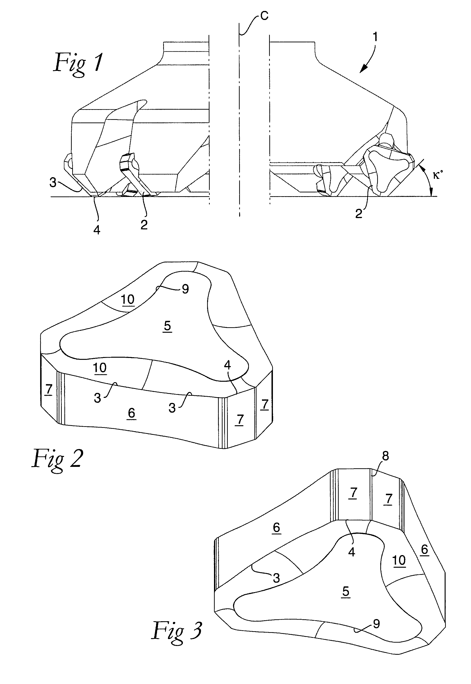
[0019]In FIG. 1, numeral 1 designates a basic body in the form of a milling cutter head, which is rotatable around a center axis designated C. Depending on the diameter of the mill, a varying number of milling inserts 2 are arranged along the periphery of the basic body, which inserts, in this case, have a triangular basic shape. In each such milling insert, main cutting edges 3 and surface-wiping secondary edges or wiper edges 4 are included. All active secondary edges 4 are situated in a common plane P, which extends perpendicularly to the center axis C. The setting angle κ between each main cutting edge 3 and the plane P amounts to 45°. When the mill, during operation, is moved rectilinearly at the same time that it rotates, the main cutting edges 3 will, in a traditional way, remove chips from the blank being machined, while the secondary edges 4 smooth down or wipe off the generated surface.

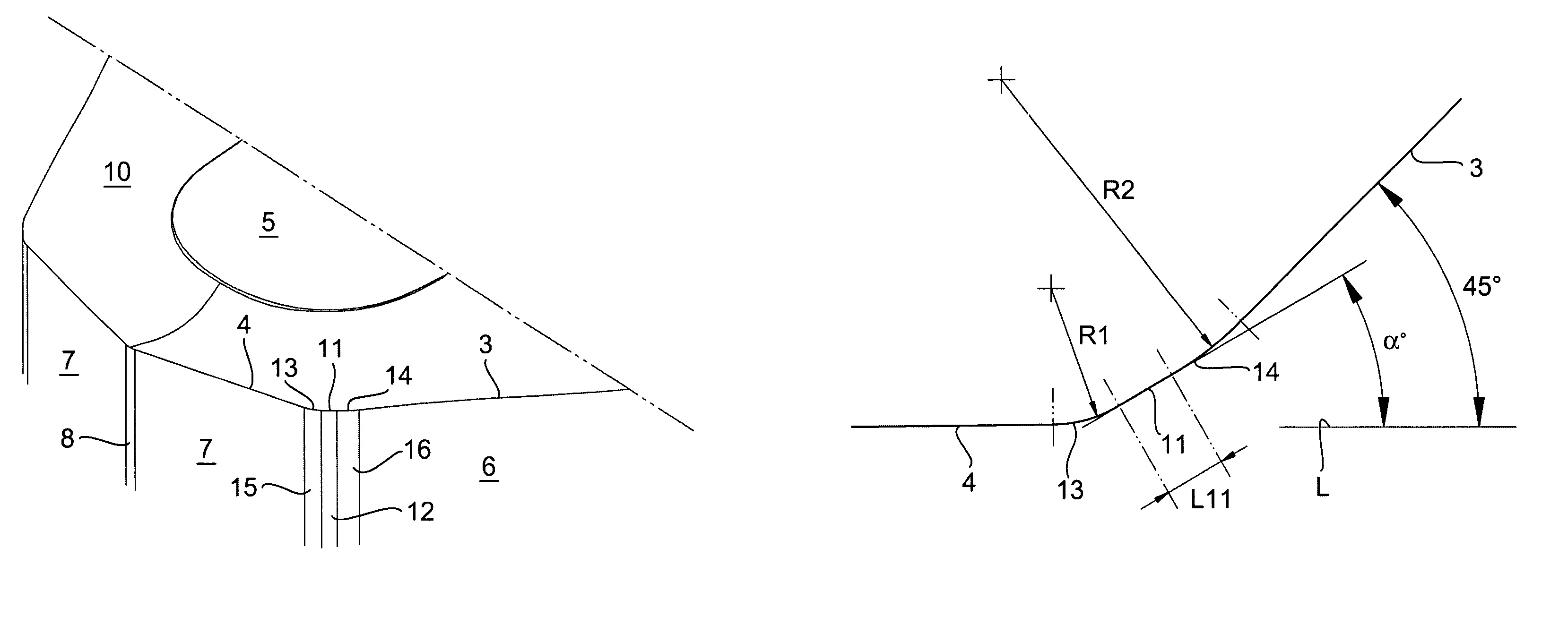
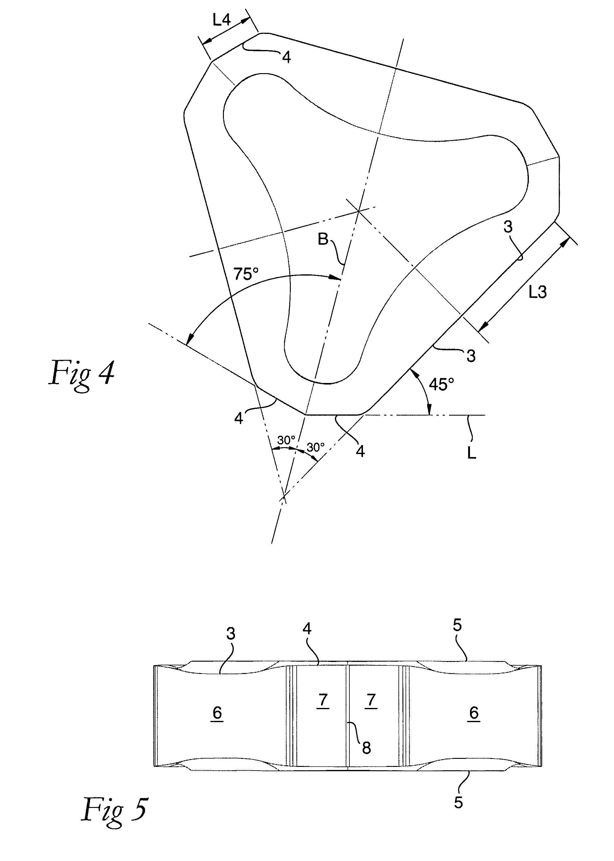
[0020]Reference is now made to FIGS. 2-8, which in detail illustrate the nature of the m...


PUM

PropertyMeasurementUnit
angleaaaaaaaaaa
radiusaaaaaaaaaa
angleaaaaaaaaaa

Abstract

A face-milling insert, including a chip-removing main cutting edge adjacent to a first clearance surface, and a surface-wiping secondary edge adjacent to a second clearance surface, the main cutting edge forming an angle of 45° with an imaginary straight line in the extension of the secondary edge. Adjacent to a third clearance surface, an intermediate cutting edge is formed between the main cutting edge and the secondary edge, the intermediate cutting edge being shorter than the main cutting edge and forming an angle within a range of 20-40° with the extension line. The intermediate cutting edge transforms into the adjacent edges via arched part edges adjacent to convex clearance surfaces.

Description

[0001]This application claims priority under 35 U.S.C. § 119 to Sweden Patent Application No. 0601402-1, filed on Jun. 27, 2006, the disclosure of which is incorporated by reference herein in its entirety.FIELD OF THE INVENTION[0002]The present invention relates generally to a face-milling insert of the type that includes a chip-removing main cutting edge adjacent to a first clearance surface, and a surface-wiping secondary edge adjacent to a second clearance surface, the main cutting edge forming an angle of 45° with an imaginary straight line in the extension of the secondary edge.BACKGROUND OF THE INVENTION[0003]For chip-removing face machining of metallic blanks or workpieces, e.g., engine-block blanks, face mills are used, which have diameters in a range of 80 mm to 700 mm, and which are equipped with replaceable milling inserts in a number that varies from 10 to over 100. A since long used milling insert for such milling cutter tools has a triangular basic shape, and is indexa...

Claims


Application Information

Patent Timeline
Patent Type & Authority Patents(United States)
IPC IPC(8): B23B27/00B23B29/00
CPCB23C5/207B23C2200/0483B23C2200/201B23C2200/203Y10T407/22B23C2200/208Y10T407/235Y10T407/23B23C2200/205B23C5/202B23C5/20B23C5/02B23B27/1603B23C5/205B23C5/06
Inventor HESSMAN, INGEMAR
Owner SANDVIK INTELLECTUAL PROPERTY AB
Why Eureka
Try Eureka