
Wind turbine apparatus

a wind turbine and wind turbine technology, applied in the direction of wind turbines with parallel air flow, wind turbine components, liquid fuel engine components, etc., can solve the problems of heavy weight and bad assembly properties, and achieve the effect of shortening the length of the wind turbine apparatus, shortening the whole length, and reducing the number of parts

Inactive Publication Date: 2009-06-16
YANMAR CO LTD
View PDF16 Cites 38 Cited by
  • Summary
  • Abstract
  • Description
  • Claims
  • Application Information

AI Technical Summary

Benefits of technology

The invention is a wind turbine apparatus that is designed to be lightweight and compact, while still supporting heavy loads such as a wind wheel and a generator. The apparatus includes a turn base on a top of a tower, a counter on the turn base, a stay on the counter, a main shaft housing and a generator housing on the stay, a bearing provided between the main shaft housing and a main shaft, a hub supported on the one side of the main shaft, and a generator rotor supported on the other side of the main shaft. The main shaft housing and the generator housing are combined, and a bearing is provided between the main shaft housing and the main shaft. The generator rotor has a backward opening, and the main shaft and the generator rotor are detachably fixed through the opening. The invention allows for a shorter wind turbine apparatus with a smaller whole length, and simplifies the installation work and reduces the number of parts.

Problems solved by technology

However, since the generator rotator is supported on the main shaft, the main shaft had to be designed long, and weight became heavy, so troubles of its heavy weights and bad assembling properties are found in the generator disclosed in the patent document 1 and 2.

Method used


Image

  • Wind turbine apparatus
  • Wind turbine apparatus
  • Wind turbine apparatus

Examples


Embodiment Construction

Best Mode for Carrying Out the Invention

[0021]Next, embodiments of the invention are described.

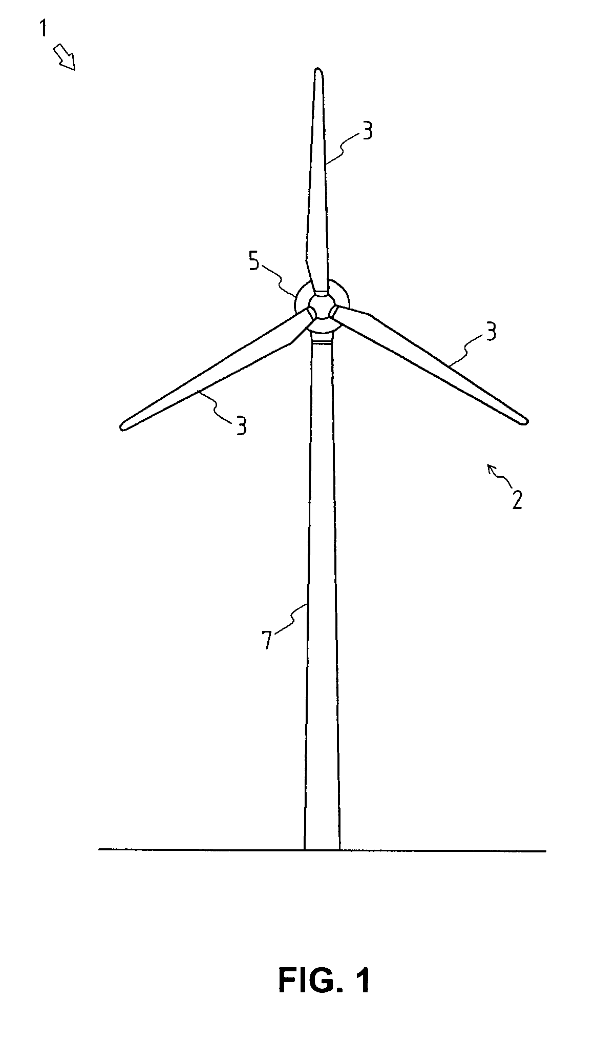
[0022]FIG. 1 is a front view that shows one embodiment of a wind turbine apparatus 1 to which the present invention is applied,

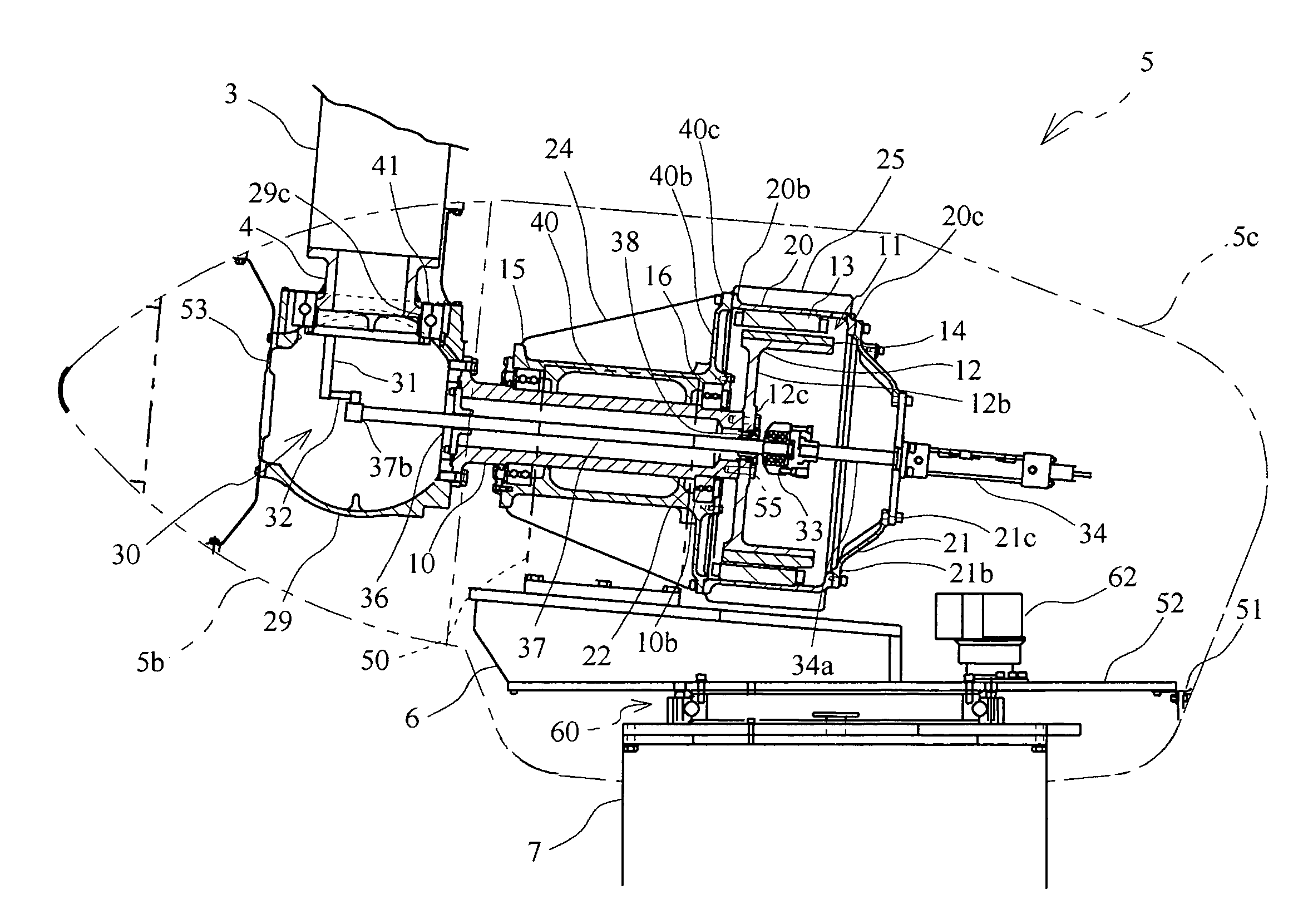
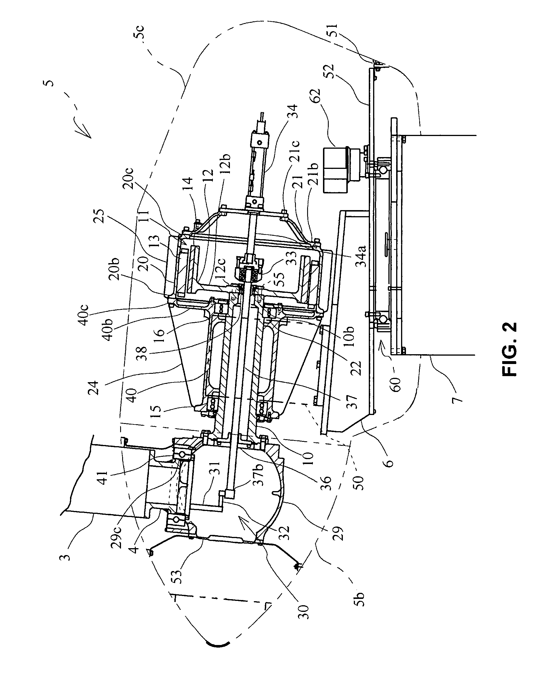
[0023]FIG. 2 is a side view cross section that shows a structure in nacelle 5 of the wind turbine apparatus 1,

[0024]FIG. 3 is an expansion side view cross section that shows around the main shaft 10.

[0025]By referring FIG. 1 and FIG. 2, the outline composition of the wind turbine apparatus 1 is described.

[0026]The wind turbine apparatus 1 of this embodiment is an apparatus that has a generator 11 that generates electrical energies by converting wind energies changed to rotational powers through a wind wheel 2, and the rotation powers is transmitted to the generator 11 connected directly with the wind wheel 2 through a main shaft 10. The wind turbine apparatus comprises, the wind wheel 2 changing wind energies into rotational power, the main shaft 10 as a rotary sha...


PUM


Abstract

Conventionally, a main shaft of the wind turbine apparatus has awkward such as heaviness or difficulties of assembling, since the length of the main shaft must be long to support a generator rotor. It is requested originally to light heaviness of a wind turbine apparatus, since it supports a wind wheel and a generator etc. on a tower at prescribed height. A hub 29 supported on the one side of the main shaft 10, a generator rotor 12 supported on the other side of the main shaft 10, the main shaft housing 40 and the generator housing 20 are combined, the generator rotor 12 having a backward opening is fixedly provided on the rear end of the main shaft 10, the main shaft 10 and the generator rotor 12 are detachably fixed through the opening, and a rotational fitting (rod bearing 33) for a pitch control shaft 37 is at least disposed at the rear space of the generator housing 20.

Description

BACKGROUND OF THE INVENTION[0001]1. Field of the Invention[0002]The invention relates to a wind turbine apparatus for generating electrical energy by means of wind energy, especially relates to a wind turbine apparatus having a variable pitch angle mechanism of wings.[0003]2. Background Art[0004]Conventionally, a wind turbine apparatus having a generator is known that it generates electrical energies by changing wind energies changed to rotation powers through wind wheel, and the rotation powers is transmitted to the generator connected with the wind wheel.[0005]There are some types of this kind of wind turbine apparatus, such as the speed-increasing type, which generate electricity by increasing the rotation speed of a wind wheel by using speed-increasing device having a gear mechanics, and such as the direct type, which generate electricity without increasing the rotation speed of the wind wheel and transmit the rotation. The latter is more excellent than the former in the point t...

Claims


Application Information

Patent Timeline
Patent Type & Authority Patents(United States)
IPC IPC(8): F03D9/00F03D7/02
CPCF03D1/001F03D9/002F03D11/0008F03D11/04H02K7/1838F05B2220/7066F05B2220/7068F05B2230/502F05B2240/14Y02E10/723Y02E10/725Y02E10/728F03D9/25F03D13/10F03D13/20F03D80/70F03D80/88Y02E10/72Y02P70/50
Inventor TAKAICHI, KAZUHIKOHITACHI, JUNICHIMIZUNO, YUKIYASUMINAMII, TOORU
Owner YANMAR CO LTD
Learn More