Common mode rejection ratio trim circuit and methodology

Active Publication Date: 2009-06-16
ANALOG DEVICES INT UNLTD
View PDF12 Cites 9 Cited by
  • Summary
  • Abstract
  • Description
  • Claims
  • Application Information

AI Technical Summary

Benefits of technology

[0003]As the offset voltage of a practical application changes with input common mode voltage, the amplifier has limited CMRR. Circuitry of various embodiments is impl

Problems solved by technology

As the offset voltage of a practical application changes wit

Method used


Image

  • Common mode rejection ratio trim circuit and methodology
  • Common mode rejection ratio trim circuit and methodology
  • Common mode rejection ratio trim circuit and methodology

Examples


Embodiment Construction

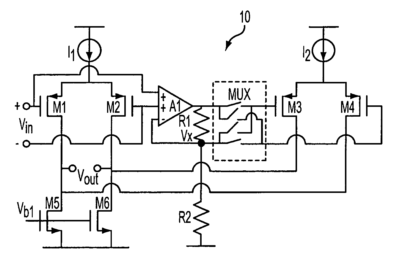
[0022]The present disclosure will be made using the example of a CMOS operational amplifier. It will become apparent, however, that the concept of the disclosure is applicable to circuits implemented in JFET and bipolar technology.

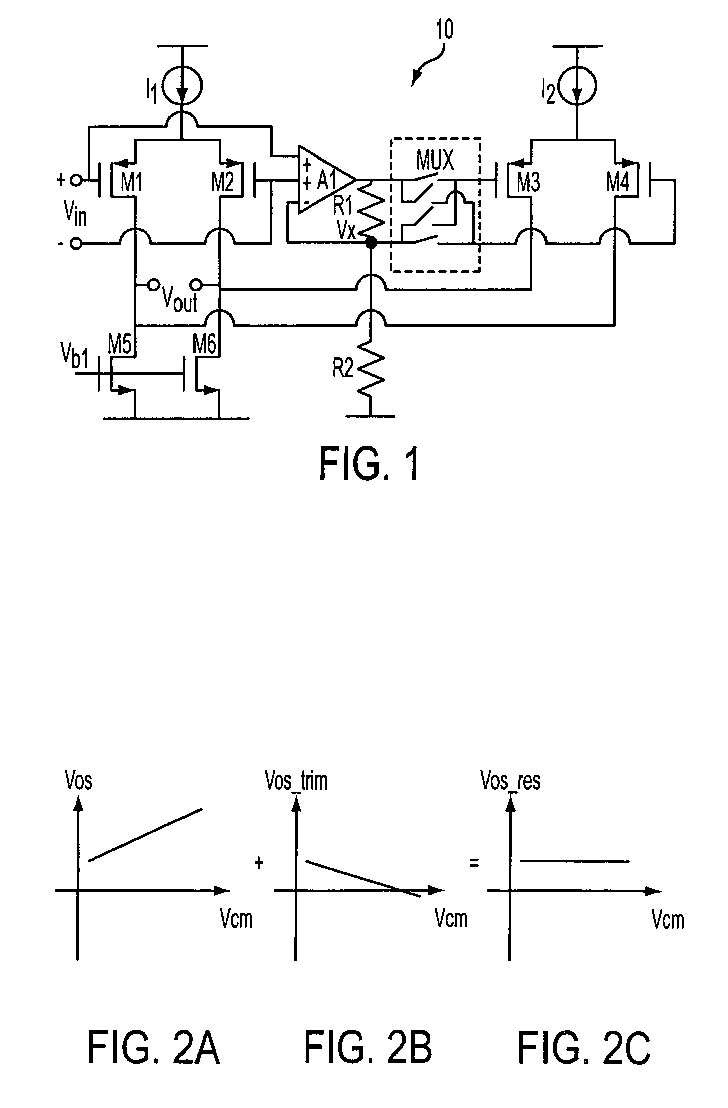
[0023]FIG. 1 shows a front stage of an exemplary operational amplifier 10 of the present disclosure, which has a trim circuit generating an offset correction voltage proportional to the input common mode voltage of the amplifier. The correction voltage is applied to reduce or cancel out the linear term in the amplifier's offset voltage versus input common mode voltage function, making its offset voltage Vos less dependent on its common mode voltage and improving CMRR.

[0024]The front stage of the operational amplifier 10 comprises an input differential pair composed of transistors M1, M2, and a CMRR trim circuit. The CMRR trim circuit comprise a dual-input differential amplifier A1 to sense the input common mode voltage of the amplifier 10, voltage divider ...


PUM


Abstract

An operational amplifier circuit includes an input differential circuit and a trim circuit for sensing the operational amplifier's input common mode voltage and generating an offset correction voltage in response thereto. The trim circuit reduces the amplifier's offset voltage dependence on input common mode voltage, and hence improves the common mode rejection ratio of the operational amplifier circuit.

Description

TECHNICAL FIELD[0001]The subject matter of this disclosure relates to amplifiers, and more particularly to circuitry and methodology for trimming the common mode rejection ratio (CMRR) of an amplifier so as to have low offset variation throughout a specified common mode range of the amplifier.BACKGROUND[0002]Differential amplifiers are commonly used in various applications. A characteristic of such amplifiers is the ability of the amplifier to reject the input common mode signal, termed common mode rejection ratio, CMRR. A large CMRR is important in precision applications, such as in instrumentation. CMRR of an ideal amplifier is said to be infinite throughout its entire range of operation. However, practical amplifiers have CMRR specifications that are finite, with value that depends upon quality of internal circuitry and component tolerances which together tend to generate an offset. Amplifier offset varies with common mode input voltage. It would be advantageous to trim CMRR so a...

Claims


Application Information

Patent Timeline
IPC IPC(8): H03F3/45
CPCH03F3/45183H03F3/45717H03F2200/453H03F2203/45048H03F2203/45371H03F2203/45424
Inventor LIU, HENGSHENG
Owner ANALOG DEVICES INT UNLTD
Why Eureka
Try Eureka