Flavor infusion cooking device and method

a technology of infusion cooking and flavor, which is applied in the direction of liquid transfer devices, grain treatment, grain husking, etc., can solve the problems of product unpredictable and uneven taste, unfavorable product quality, and numerous drawbacks of system types, so as to achieve greater control over the cooking process, more flexibility in utilization and directing, and quick attachment

Inactive Publication Date: 2009-06-23
ZIMMERMAN HARRY
View PDF57 Cites 23 Cited by
  • Summary
  • Abstract
  • Description
  • Claims
  • Application Information

AI Technical Summary

Benefits of technology

[0004]The invention provides a device and method for cooking food that offers improvement over other conventional cooking systems, whether they be grills, ovens, barbeques, and the like, that provides a device and method for infusing the food being cooked with additional moisture and / or flavor. The system includes a preferably substantially closed pressurized system that employs an independent and separate flavor reservoir(s), or in the alternative, a fluid compartment with a removable flavor reservoir, a separate flavor infuser or multitude of infusers that are adapted to pierce or penetrate through the surface of the food being cooked (e.g., meat, fowl, fish, vegetables, etc.) or enter a container for such items being cooked, and a connector, either rigid (manifold) or flexible, that connects the flavor reservoir(s) to the flavor infuser(s). The connector can have a quick release connector to allow an infuser to be connected and disconnected easily and quickly.
[0006]In short, heat is used to turn a liquid such as water, a marinade (e.g., soy sauce based), a bouillon, etc., to a vapor or heated liquid. By heating the substantially enclosed flavor reservoir, the corresponding increase in pressure results in the (flavored) vapor or heated liquid being propelled out of our reservoir through the connecting plumbing or channels to the flavor infuser which is designed to pierce through the outer layers of the food to be cooked (or a container for such food) so that the pressurized moisture and flavor flow out of relief holes within infusers that are now situated within the body of the item being cooked or container therefor. This action thereby acts to marinate, flavor and / or further moisturize the item being cooked. In addition, because the flavor infusers are embedded within the body of the item being cooked, conductivity can tend to heat the infusers, which in turn transfer heat into the interior of the item being cooked which itself leads to more even and quicker cooking time in that not only is the food being cooked from the outside in, but the infusers will transfer heat energy into the food, thereby accelerating the cooking time.
[0007]By utilizing a flavor reservoir that is independent from the infusers, the device can assure that the composition of the flavor being infused into the item being cooked is more consistent throughout, first because the actual flavor and moisture being delivered is from the same source and also because the environment that is producing the flavored or moisture imbuing vapor is all being produced under a consistent environmental circumstance (e.g., same BTU's being consumed uniformly). In addition, other advantages of having an independent flavor reservoir allows for better control in matching the placement of the reservoir with the heat source. In the exemplary designs of the invention, the reservoir can either utilize the existing heating source of the cooking medium (such as the burners of an oven, the electric coils, gas burner or charcoal of a grill) or the reservoir can alternately be equipped with its own dedicated heat source allowing for even more finite adjustments independent of the internal temperature of the cooking medium. In any event, the net result is a more consistent and controllable environment for the heating and distribution of the flavor and moisture to the item being cooked.
[0010]By providing the infusers and reservoir as separate components, and having an intermediary connecting channel or plumbing, the device provides more flexibility in the utilization and directing of the flavor and moisture that leaves the flavor reservoir. For example, in a system provided with multiple infusers, the infusers can be provided in parallel lines or areas in order to create different zones, allowing for greater control over the cooking process. For example, by employing a shut off valve, a user can shut of some zones while keeping others open, or certain flavors can be added to some zones while directing other flavors to other zones. In addition, because the connection plumbing can be made out of a flexible line, one or more connecting nipples can be provided along or at the end of the line allowing for accessories to be quickly attached when needed for specific application. For instance, when cooking a roast, longer infusers might be inserted, when cooking fowl movable infusers might be connected to attach to the irregular shape, etc., and an infuser designed to infuse a container can be provided (e.g., to cook items placed therein, such as vegetables.) Having intermediary channeling or plumbing allows moving of the infusers without compromising the optimum positioning of the flavor reservoir. This is an important benefit in that it allows utilizing a system having a movable infuser grid that can be moved up or down to accommodate different thickness of meat, etc. From a safety perspective, having an intermediate section between the infuser and reservoir also allows inclusion of a pressure relief valve in a non-conspicuous place that would be needed in any pressurized system.
[0011]Finally, because the reservoir is bifurcate from the infuser, there is great flexibility in how the infusers are designed and used. For instance, a series of infusers can be affixed to a grid so that instead of placing the infuser into the item being cooked, we can now place the item being cooked over the fixed infusers. This does two things, first because heat always rises, it lends itself to a more efficient and effective operation for both the conductivity of the infusers in heating the food itself and the rising of the vapors into the interior of the item being cooked. Of course, this invention contemplates other circumstances such as when the infusers are placed into the item being cooked from the top. In addition, this also allows for the user to turn the item being cooked as necessary with ease, which is required for many items being cooked, and something that would be difficult with other systems.
[0012]To the extent that some infusers in a grid pattern of infusers may not penetrate the item being cooked, the vapor exiting the non-penetrating infusers can act to provide a misting of flavor and / or moisture to the exterior of the item being cooked. Also, the system may also further include a valve system which prevents flavor and / or moisture from exiting an infuser which has not penetrated an item being cooked, e.g. spring loaded valves which only open up when depressed and / or a mechanical blocking mechanism for the individual infusers. Furthermore, the system can include a relief valve that prevents excess pressure from building up in the reservoir, pipes, and / or infusers and / or a one-way check valve to prevent pressurized fluid from back flowing.

Problems solved by technology

This type of system has numerous drawbacks and limitations.
Furthermore, since each stick is loaded individually with flavorings, there is no assurance that the concentration of ingredients would remain uniform in all the sticks.
Also, since each stick can be exposed to different temperatures based on logistical positioning within the cooking medium, the concentration of flavor in the resulting vapor being infused can vary from point to point, resulting in a product with unpredictable and uneven taste.
In addition, utilizing a single stick can create other logistical problems.
There are likewise obvious issues dealing with the necessity of being able to turn over the item being cooked with the flavor stick and reservoir still attached.
Finally, there are logistical limitations in that space and weight considerations would limit the amount of flavor, etc. that could be stored without having to be concerned with the stick toppling over or taking up too much space on the grill.

Method used


Image

  • Flavor infusion cooking device and method
  • Flavor infusion cooking device and method
  • Flavor infusion cooking device and method

Examples


Embodiment Construction

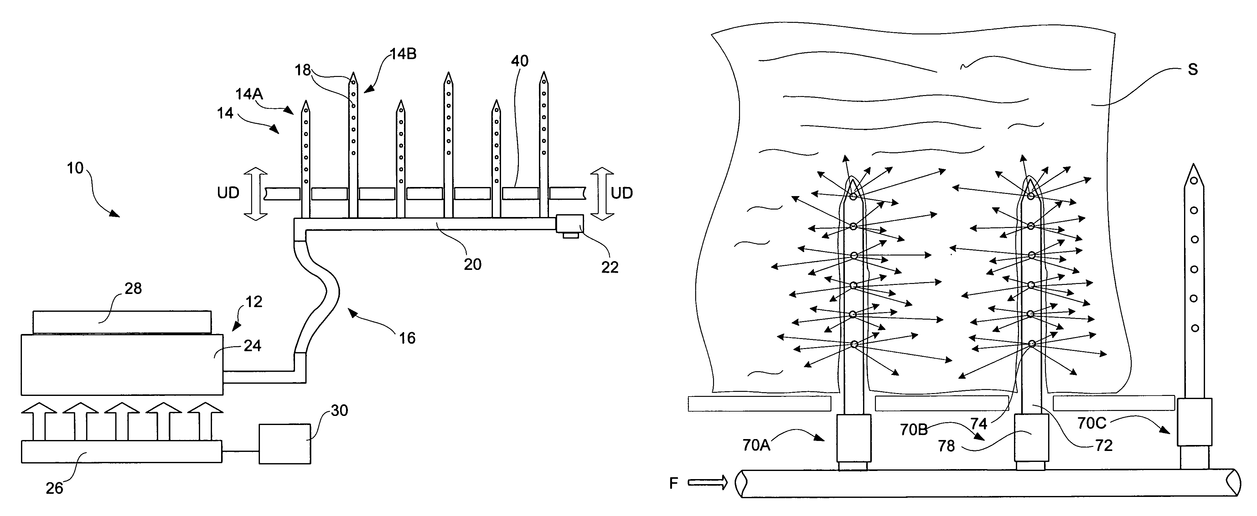
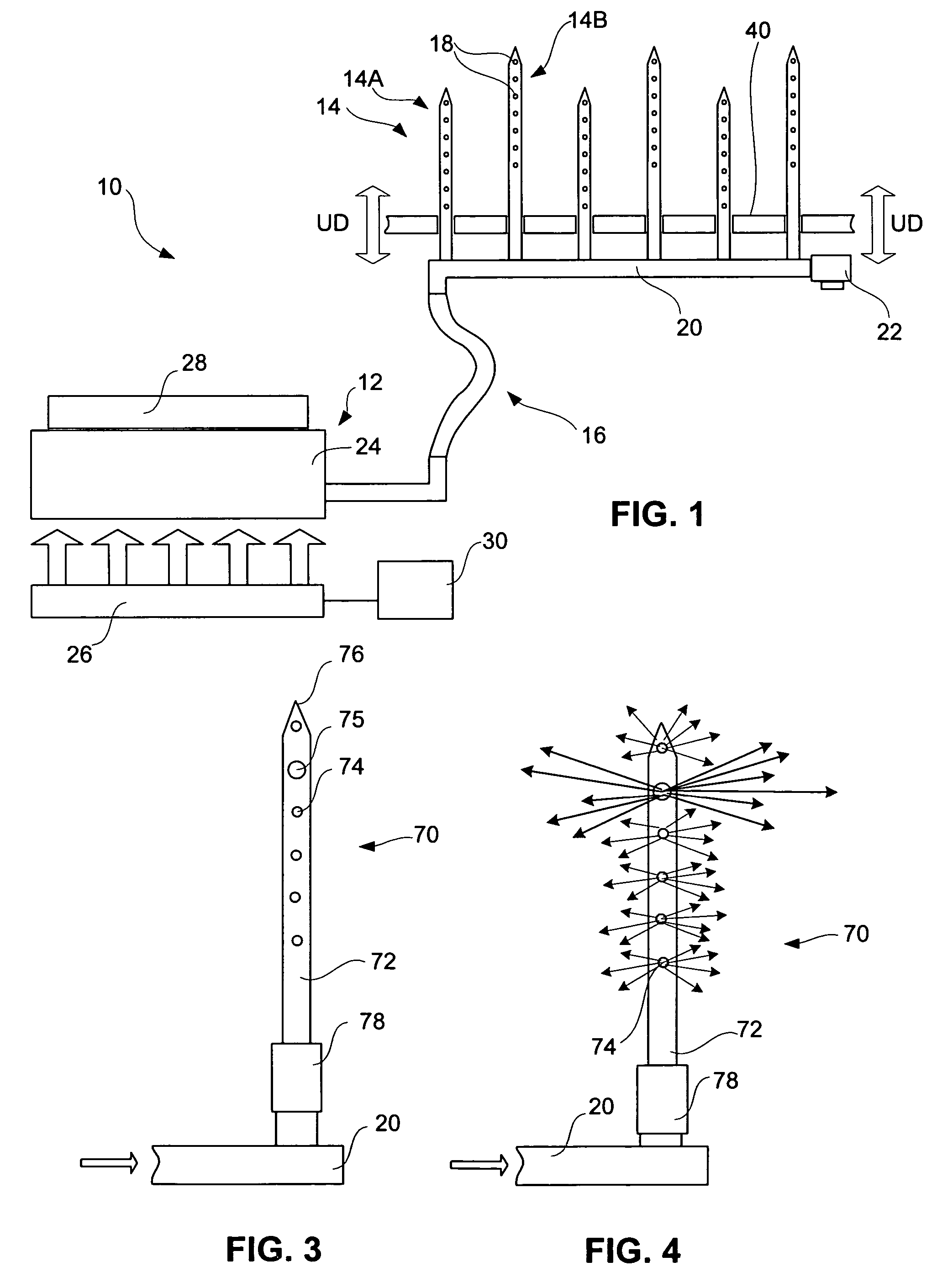
[0029]Referring to FIG. 1, there is shown a diagrammatic side view of an exemplary embodiment of the flavor infusion device 10. The flavor infusion device 10 comprises a reservoir 12, one or more infusers 14A and 14B, and a conduit 16 that carries fluid from the reservoir 12 out through apertures 18 in the infusers 14. As used herein, the word “fluid ” means liquid, vapor and gas. The infusers 14 preferably are adapted to penetrate an item being cooked (not shown). A plurality of infusers 14 are shown attached to a fluid manifold 20 connected to the conduit 16. The lengths of the infusers 14A and 14B can be different and / or the positioning of their aperture 18 can be varied, if desired. The conduit 16 is shown connecting between the main compartment 24 and the manifold 20. A pressure relief valve 22 can be included to release any excessive pressure build-up in the device. The reservoir 12 has a main compartment 24 that retains liquids and any solids, and a heat source 26 is used to ...


PUM


Abstract

A device and method for infusing a heated fluid into an item being cooked. The device includes infusers adapted to penetrate into the item being cooked, a fluid reservoir for containing and heating a separate fluid that will be infused into the item being cooked, and a conduit connecting the infuser and the fluid reservoir. The infusers are contained in a cooking unit.

Description

BACKGROUND[0001]The invention relates to devices and method for cooking food, and more particularly to a device and method for infusing food with flavor and moisture, and also cooking food more evenly and quickly.[0002]In the past, attempts have been made to harness the benefits of thermodynamic physics by developing and using flavor sticks. These flavor sticks are self-contained units that are inserted into the food being cooked allowing the subsequent internal pressure build up caused by heating to push out the flavors that were preloaded in the flavor stick. This type of system has numerous drawbacks and limitations. For example, by their design, each stick (when more than one is used) would have to be placed in different strategic positions in order to deliver a diverse demographical flavor footprint. This can result in each stick being exposed to different temperatures, with each stick thusly producing a different level of penetration since the internal pressure, which is a fun...

Claims


Application Information

Patent Timeline
Patent Type & Authority Patents(United States)
IPC IPC(8): A47J37/00A23L1/22A23L13/00A23L27/00
CPCA23L1/01A23L1/0114A23L1/0121A23L1/3182A47J37/06A47J43/18A47J2027/043A23L5/10A23L5/12A23L5/13A23L13/72
Inventor ZIMMERMAN, HARRY
Owner ZIMMERMAN HARRY
Why Eureka
Try Eureka