Sealing device

a sealing device and sealing lip technology, applied in the direction of engine components, mechanical equipment, manufacturing tools, etc., can solve the problems of short life of sealing lip and short life of opposing contact side, and achieve the effect of reliable separation of impurity-laden coolan

Active Publication Date: 2009-06-23
SMS DEMAG AG
View PDF10 Cites 0 Cited by
  • Summary
  • Abstract
  • Description
  • Claims
  • Application Information

AI Technical Summary

Benefits of technology

[0013]So that the impurity-laden coolant cannot pass around the second sidepiece 13 and arrive in the labyrinth 15 formed here, the second sidepiece 13 has a separator edge 16, which, while the second sidepiece 13 is turning, ensures an even more reliable separation of the impurity-laden coolant.

Problems solved by technology

During hard rolling operation, the ring seal shown here is continuously exposed to the coolant, which is laden with impurities, as a result of which the sealing lip has only a very short life-span.
In addition, the opposing contact surface, that is, the end surface of the roll, is subjected to disproportionate wear by the impurities present in the coolant, so that this opposing contact side also has only a short life-span.

Method used


Image

  • Sealing device
  • Sealing device

Examples


Embodiment Construction

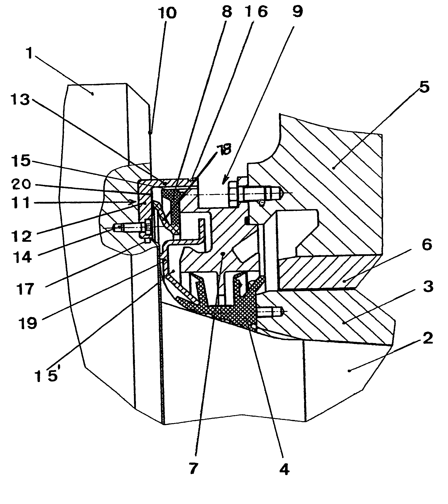
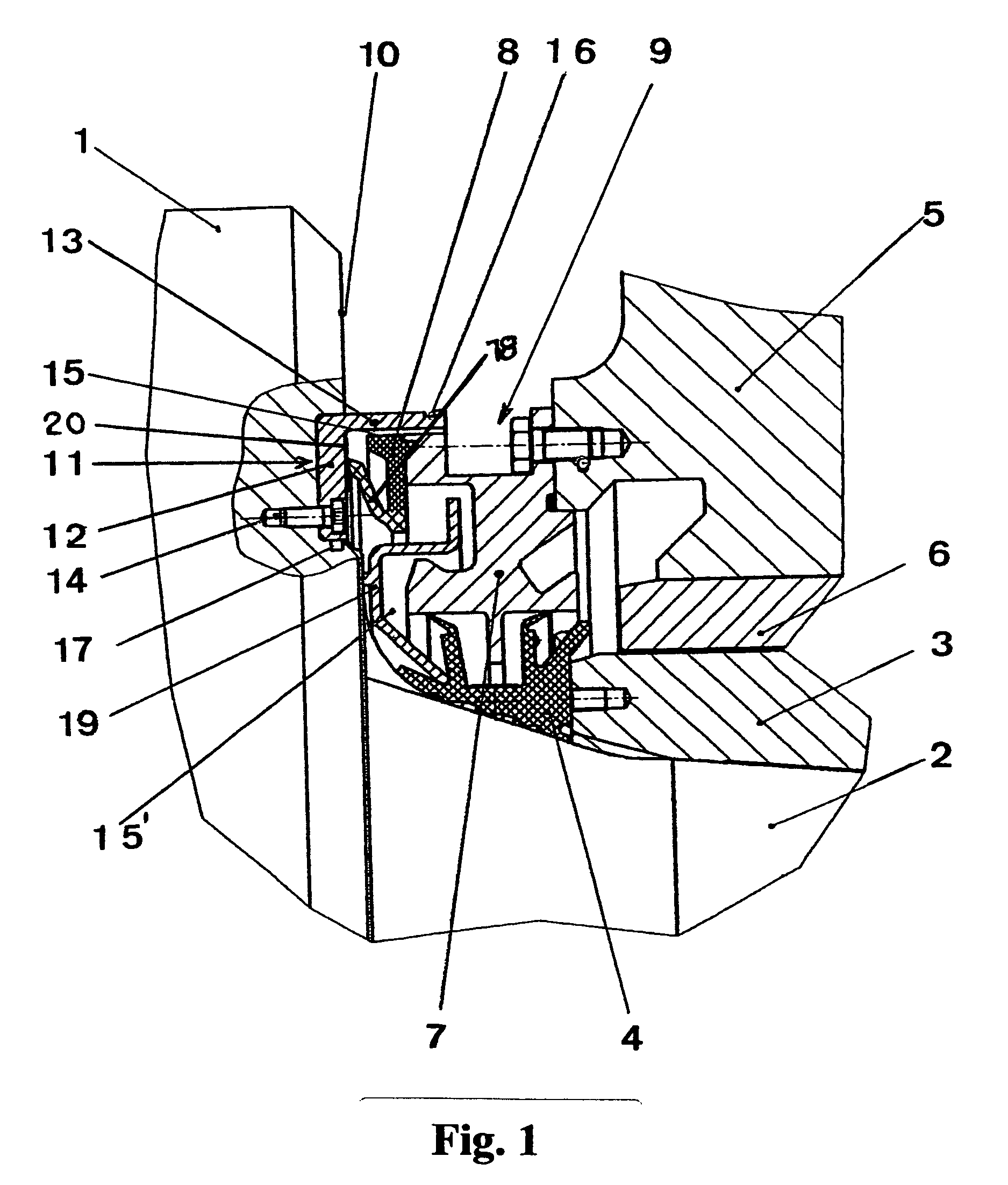
[0015]In the area of the first sidepiece 12 and the end surface 10, a lubricant reservoir 17 is provided, from which lubricant can travel to the contact surface between the sealing lip 18 and the first sidepiece 12. An appropriate lubricating action is thus provided, which also helps to increase the life-span of the seal. An area 20 of the first sidepiece 12, which is in contact with the sealing lip 18, is at least one of hardened and subjected in certain areas to at least one of plasma nitriding and controlled oxidation.

[0016]Between the ring seal 8 and the neck seal 4, another ring-shaped profile 19 is provided to ensure that a labyrinth 15′ with the greatest possible number of turns is formed.

LIST OF REFERENCE NUMBERS

[0017]1 roll[0018]2 roll neck[0019]3 neck bush[0020]4 neck seal[0021]5 bearing housing[0022]6 bearing bush[0023]7 ring-like extension[0024]8 ring seal[0025]9 drain groove[0026]10 end surface[0027]11 L-shaped profile[0028]12 first sidepiece[0029]13 second sidepiece[00...


PUM

PropertyMeasurementUnit
areaaaaaaaaaaa
areasaaaaaaaaaa
hardnessaaaaaaaaaa

Abstract

The invention relates to a sealing device for roller bearings, comprising a journal seal (4), which is arranged upstream on the roller-ball side of the annular seal (8) which is connected in a rigid manner to an annular projection (7) of the bearing housing (5). The sealing lip (18) of the sealing device is applied to the front side (10) of the roller (1) by means of a sealing contact. The aim of the invention is to improve the sealing device in such a manner that the sealing lip of the annular seal is barely impinged upon by cooling means mixed by impurities, making it long lasting and ensuring that no undesired water can penetrate into said outlet. According to the invention, an L-shaped profile (11), in the cross-section, is rigidly connected to the first side (12) thereof by means of the front side (14) of the roller (1), such that the sealing lip (18) is applied to areas of the first side (12); such that the second side (13) of the L-shaped annular profile (11) is sealed to the roller balls at a certain distance from the annular seal (8) and regions of the annular projection (7); and such that the annular projection (7) comprises an outlet groove (9) which is arranged on the outer side and is open towards the outside.

Description

BACKGROUND OF THE INVENTION [0001]The invention pertains to a sealing device for roll bearings with a neck seal, which is preceded on the roll barrel side by a ring seal, which is permanently connected to a ring-like extension of the bearing housing, the sealing lip of the ring seal resting with sealing contact against the end surface of the roll.[0002]A sealing device of this type is known from, for example, DE 694 10 752 T2. During hard rolling operation, the ring seal shown here is continuously exposed to the coolant, which is laden with impurities, as a result of which the sealing lip has only a very short life-span. In addition, the opposing contact surface, that is, the end surface of the roll, is subjected to disproportionate wear by the impurities present in the coolant, so that this opposing contact side also has only a short life-span. The ring seals, furthermore, have openings in their lower area, which allow the impurity-laden coolant which has arrived in the labyrinth i...

Claims


Application Information

Patent Timeline
Patent Type & Authority Patents(United States)
IPC IPC(8): F16J15/34F16C33/74F16C33/76F16J15/32B21B31/07F16C13/02F16J15/447
CPCB21B31/078F16C13/02F16C33/74F16C2322/12B21B31/07F16C33/72F16C33/76F16J15/44
Inventor ROEINGH, KONRADKELLER, KARLHUCKER, ROLF
Owner SMS DEMAG AG
Why Eureka
Try Eureka