Distortion correction for projector

a projector and distortion correction technology, applied in the field of distortion correction techniques, can solve the problems of image distortion difficulty in correcting image distortion with accuracy for display on the projection surface, and no consideration of such image display areas, etc., and achieve the effect of accurately correcting any distortion observed

Active Publication Date: 2009-06-23
SEIKO EPSON CORP
View PDF13 Cites 26 Cited by
  • Summary
  • Abstract
  • Description
  • Claims
  • Application Information

AI Technical Summary

Benefits of technology

[0007]An advantage of some aspects of the invention is to accurately correct any distortion observed in images to be displayed on projection surfaces.
[0009]With such an image processing device of the first aspect, any original image data is so corrected that a target distorted image is formed in a target formation area, which is defined by the relationship between a reference display area and a reference formation area, and the generation result is corrected image data. That is, in this image processing device, the corrected image data is generated with consideration given to the target display area that is determined based on the current value of a parameter so that any distortion observed in images can be corrected with accuracy for display on a projection surface.

Problems solved by technology

With such low-angle image projection, the resulting images displayed on the projection surfaces suffer from distortion.
With such a previously-known technique, however, there still remains a difficulty in correcting image distortion with accuracy for display on the projection surface.
However, no consideration has been given to such image display areas, and in Patent Document 1, there is indeed a description of changing the shape of an image formed on a liquid crystal panel depending on the position of a projection lens, but there is no disclosure about the specific technique of making such changes.
When the target formation area does not fit in the image formation section, the resulting image is not fully displayed on the projection surface.

Method used


Image

  • Distortion correction for projector
  • Distortion correction for projector
  • Distortion correction for projector

Examples


first embodiment

A. First Embodiment

[0043]A-1. Configuration of Projector

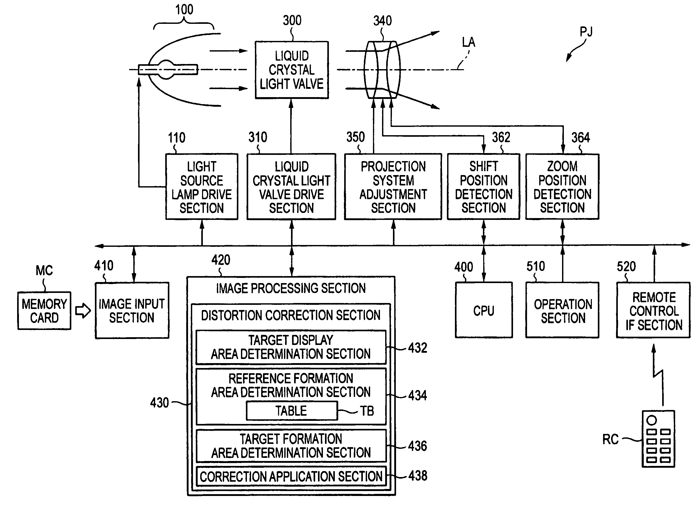
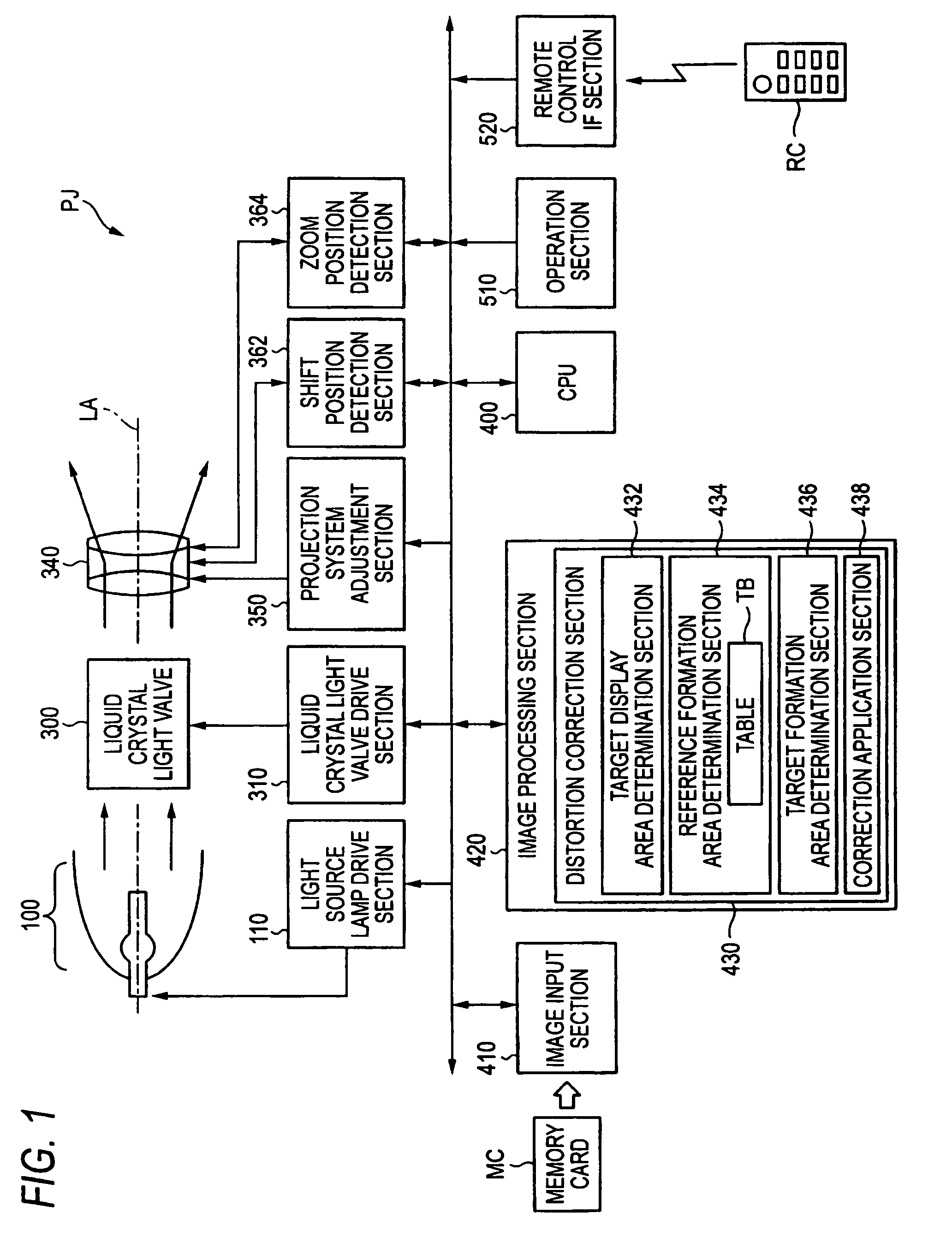
[0044]FIG. 1 is a block diagram showing the configuration of a projector PJ in a first embodiment. The projector PJ is configured to include an illumination system 100, a liquid crystal light valve 300, and a projection system 340. In FIG. 1, the optical system is shown quite simplified.

[0045]The projector PJ also includes a light source lamp drive section 110, a liquid crystal light valve drive section 310, a projection system adjustment section 350, a shift position detection section 362, a zoom position detection section 364, a CPU (Central Processing Unit) 400, an image input section 410, an image processing section 420, an operation section 510, and a remote control interface (IF) section 520. The CPU 400 is in charge of exercising control over the projector.

[0046]The light source lamp drive section 110 drives a light source lamp included in the illumination system 100. The liquid crystal light valve drive section 310 driv...

second embodiment

B. Second Embodiment

[0114]B-1. Configuration of Projector

[0115]FIG. 13 is a block diagram showing the configuration of a projector PJB in a second embodiment. FIG. 13 is almost the same as FIG. 1 except for an image processing section 420B, more specifically, a distortion correction section 430B. In this embodiment, a setting memory 440 is provided as alternatives to the projection system adjustment section 350, the shift position detection section 362, and the zoom position detection section 364 in FIG. 1.

[0116]The setting memory 440 is storing setting values, indicating the position and magnification of a distorted image for formation on the liquid crystal light valve 300. The position and magnification of a distorted image for formation on the liquid crystal light valve 300 specify the position and magnification of a regular image for display on the screen. The setting value for the position is represented by the movement direction and amount from any predetermined position of a ...


PUM


Abstract

An image processing device for a projector including an image formation section that emits light of an image, and a projection system that projects the emitted light onto a projection surface. The image processing device includes: a target display area determination section that determines, in a display area serving as a reference on the projection surface, based on a current value of a parameter, any of target display areas set for values possibly taken by the parameter within an allowable range to be targeted on a distortion-free image for display on the projection surface; a reference formation area determination section that determines, corresponding to the reference display area, based on information about a projection angle of the projector with respect to the projection surface, a reference formation area to be formed with a virtual distorted image that is supposed to be formed in the image formation section when the distortion-free image is displayed in the reference display area; and a correction application section that generates corrected image data for supply to the image formation section by correcting any provided original image data to form a target distorted image in a target formation area, which corresponds to the target display area as is defined by a relationship between the reference display area and the reference formation area, and is formed with the target distorted image that is supposed to be formed in the image formation section when the distortion-free image is displayed in the reference display area.

Description

BACKGROUND[0001]1. Technical Field[0002]The present invention relates to image processing for projectors and, more specifically, to a distortion correction technique for images to be displayed on projection surfaces.[0003]2. Related Art[0004]Projectors generally display images from a low angle onto projection surfaces. With such low-angle image projection, the resulting images displayed on the projection surfaces suffer from distortion. For this reason, in a projector of Patent Document 1 (JP-A-2002-72351), any distorted image is formed in an internally-provided image formation section exemplified by a liquid crystal light valve so that the resulting image to be displayed on the projection surface becomes free from distortion. Note here that the low-angle image projection denotes the projection technique in which the light source optical axis of a projector is not vertical to a projection surface.[0005]With such a previously-known technique, however, there still remains a difficulty...

Claims


Application Information

Patent Timeline
Patent Type & Authority Patents(United States)
IPC IPC(8): G03B21/14
CPCH04N9/3185H04N5/74
Inventor FURUI, SHIKI
Owner SEIKO EPSON CORP
Why Eureka
Try Eureka