
LED lamp with plural radially arranged heat sinks

a technology of led lamps and heat sinks, which is applied in the direction of semiconductor devices for light sources, lighting and heating apparatus, planar light sources, etc., can solve the problems of increasing power consumption and heat generation, increasing the heat dissipation problem of led units b>13/b>, and increasing the heat dissipation area. , to achieve the effect of enhancing the overall heat dissipation efficiency and increasing the total heat dissipation area

Inactive Publication Date: 2009-06-23
HONG KUAN TECH
View PDF3 Cites 48 Cited by
  • Summary
  • Abstract
  • Description
  • Claims
  • Application Information

AI Technical Summary

Benefits of technology

[0009]A primary object of the present invention is to provide a LED lamp, which is provided with a heat-dissipating module to substantially increase total heat-dissipating area, so as to improve and enhance the overall heat-dissipating efficiency.
[0011]A third object of the present invention is to provide a LED lamp, which is provided with at least one LED unit for generating a light source and a cover member for evenly projecting the light source and providing a dust-proof effect.
[0012]A fourth object of the present invention is to provide a LED lamp, which is provided with at least one LED unit for generating a light source, a metal base, and a light reflection member for reflecting and concentrating the light source, so as to prevent the loss of the light source and to cover the metal base for the purpose of decoration.

Problems solved by technology

However, traditional projection lamps are generally halide projection lamps with a specification of 110 Volt, which results in increasing power consumption and generation of heat, so that the life span thereof is shortened relatively (only about several months).
With the trend of higher and higher power rate, the traditional halide projection lamps are uneconomical and may cause an environmental issue; while the generated heat easily causes accidents such as cable fires.
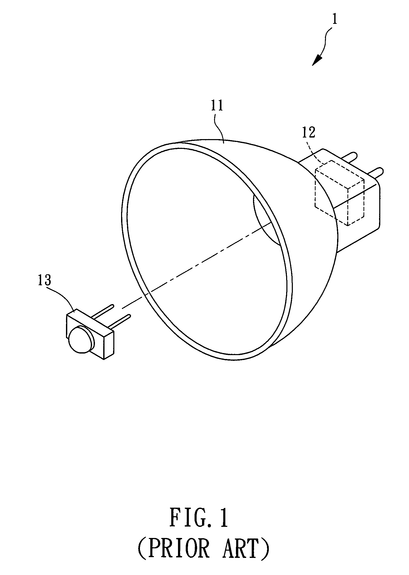
Although the illumination of the LED unit 13 is continuously increasing with the advance of lamp technology, the heat-dissipation problem of the LED unit 13 is more and more serious.
Even though the traditional LED projection lamp 1 has the heat-dissipation problem, the traditional LED projection lamp 1 is still not provided with any heat-dissipation structure for dissipating heat.
Hence, the traditional LED projection lamp 1 can only use the LED unit 13 with a maximum power specification up to 1 Watt due to the heat-dissipation problem, so that the total illumination of the traditional LED projection lamp 1 is limited and the traditional LED projection lamp 1 cannot be used to completely replace the traditional halide projection lamp.
As a result, the traditional halide projection lamp with the higher power consumption and the more heat generation still has a considerable market share, which leads to unnecessary waste of the limited energy resources in the world.

Method used


Image

  • LED lamp with plural radially arranged heat sinks
  • LED lamp with plural radially arranged heat sinks
  • LED lamp with plural radially arranged heat sinks

Examples


Embodiment Construction

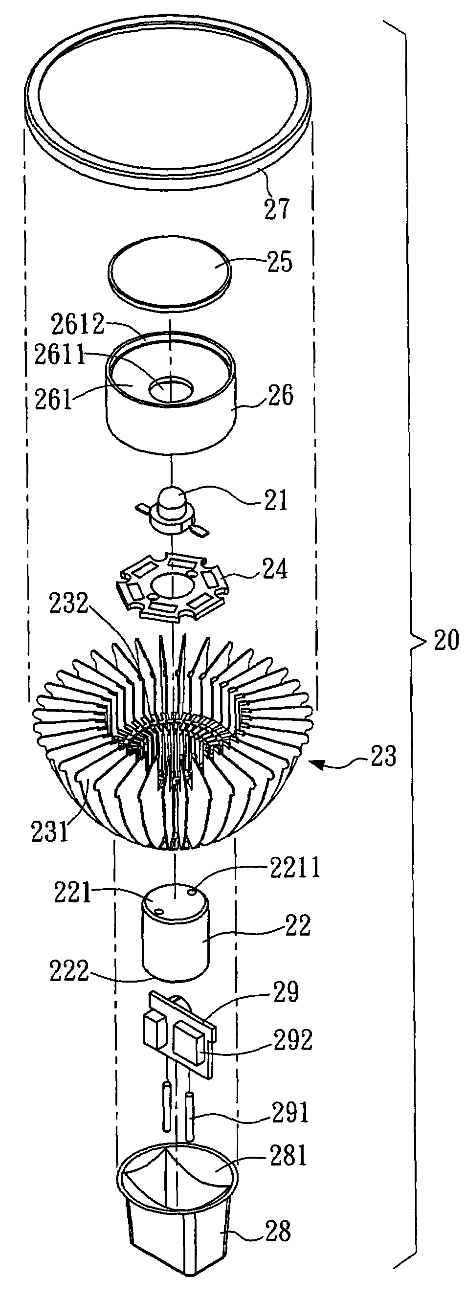
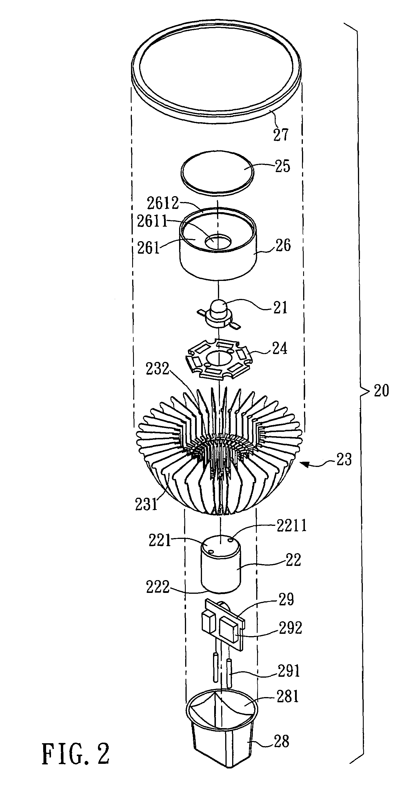
[0030]Referring now to FIGS. 2 and 3, an exploded perspective view and an assembled perspective view of a LED (light emitting diode) lamp according to a first preferred embodiment of the present invention are illustrated. As shown, the LED lamp designated by numeral 20 comprises at least one LED unit 21, a thermally-conductive post 22, a heat-dissipating module 23, at least one metal base 24, at least one cover member 25, at least one light reflection member 26, a sheath 27, a foundation 28, and a printed circuit board (PCB) 29. The heat-dissipating module 23 is provided with a plurality of heat sinks 231.

[0031]Referring still to FIGS. 2 and 3, in the first preferred embodiment of the present invention, the thermally-conductive post 22 is a column having an upper end 221 and a lower end 222, wherein the upper end 221 is provided with at least one through hole 2211. The thermally-conductive post 22 is preferably made of metal or alloy with a high thermal conductivity, such as iron, c...


PUM


Abstract

A LED lamp includes at least one LED unit, a thermally-conductive post, a heat-dissipating module, at least one metal base, at least one cover member, at least one light reflection member, a sheath, a foundation, and a printed circuit board (PCB). The heat-dissipating module is provided with a plurality of heat sinks, each of which has one end serially connected to each other and radially arranged on an outer periphery of the thermally-conductive post, and the other end apart from each other, so as to constitute the heat-dissipating module. The sheath is used to surround and position the heat sinks, so that the heat sinks are confined. The LED unit is mounted on the metal base, which is received in a step portion formed on a central portion of each of the heat sinks. The light reflection member is provided with a curved focusing portion for focusing a light source projected by the LED unit following by outputting the light source via the cover member. The heat generated by the LED unit can be dissipated to the thermally-conductive post via the metal base, and then the heat will be dissipated from the thermally-conductive post to the heat-dissipating module constructed from the heat sinks that are in contact with the thermally-conductive post, so as to dissipate the heat to the atmosphere.

Description

BACKGROUND OF INVENTION[0001]1. Field of the Invention[0002]The present invention relates to a LED (light emitting diode) lamp, and more particularly to a LED lamp having a LED unit and a plurality of heat sinks surrounding the LED unit for efficiently dissipating the heat generated by the LED unit.[0003]2. Description of the Prior Art[0004]Presently, projection lamps have a considerable market share among all of commercially available lamps. Especially, when various power-saving electronic lamps are used to replace traditional fluorescent lamps, the projection lamps still play an important role due to the fact that the projection lamps further providing a particular illuminating effect. For example, when decorating various house environments, exhibition places, showrooms, or restaurants, the projection lamps are inevitably used to create a mood for focusing on exhibited trade articles or decorations. Because the projection lamps have the considerable market share, various specifica...

Claims


Application Information

Patent Timeline
Patent Type & Authority Patents(United States)
IPC IPC(8): F21V29/00B60Q1/06
CPCF21V29/004F21K9/137F21V29/773F21Y2101/02F21Y2105/001F21Y2105/10F21K9/233F21Y2115/10F21V29/70
Inventor TSAI, CHIN SUNG
Owner HONG KUAN TECH
Learn More