Catheter having a readily bondable multilayer soft tip

a multi-layer soft tip and catheter technology, applied in balloon catheters, surgery, coatings, etc., can solve the problems of tearing/damage of the tip and disadvantageously affecting the so as to improve the processability and deliverability of the catheter, improve the integrity of the tip, and improve the effect of the deliveryability

Active Publication Date: 2009-06-23
ABBOTT CARDIOVASCULAR
View PDF17 Cites 51 Cited by
  • Summary
  • Abstract
  • Description
  • Claims
  • Application Information

AI Technical Summary

Benefits of technology

[0011]The first polymeric material is preferably a relatively high Shore durometer material providing a non-tacky inner surface along at least a section of the distal tip. For example, relatively high durometer polyamides are typically non-tacky whereas relatively low durometer polyamides are tacky (adhesive stickiness), at least at temperatures commonly encountered during assembly or use of the catheter. Such tacky materials have an increased risk of adhering to a processing mandrel during assembly of the catheter, potentially resulting in tearing / damage of the tip. Moreover, during use of the catheter in an interventional medical procedure, such tacky materials can cause “locking” of the guidewire, thus disadvantageously affecting deliverability of the catheter. However, unlike attempts to improve processability and deliverability of the catheter by having a distal end with an inner lubricious layer of a material such as high density polyethylene (HDPE) or polytetrafluoroethylene (PTFE) and an outer layer of a bondable material for heat fusion bonding to the balloon, both the inner and outer layers of the distal tip of the invention are individually heat fusion (i.e., thermally) bondable to the balloon (and do form a heat fusion bond to the balloon). As a result, tip integrity is improved in a catheter of the invention.

Problems solved by technology

Such tacky materials have an increased risk of adhering to a processing mandrel during assembly of the catheter, potentially resulting in tearing / damage of the tip.
Moreover, during use of the catheter in an interventional medical procedure, such tacky materials can cause “locking” of the guidewire, thus disadvantageously affecting deliverability of the catheter.

Method used


Image

  • Catheter having a readily bondable multilayer soft tip
  • Catheter having a readily bondable multilayer soft tip
  • Catheter having a readily bondable multilayer soft tip

Examples


Embodiment Construction

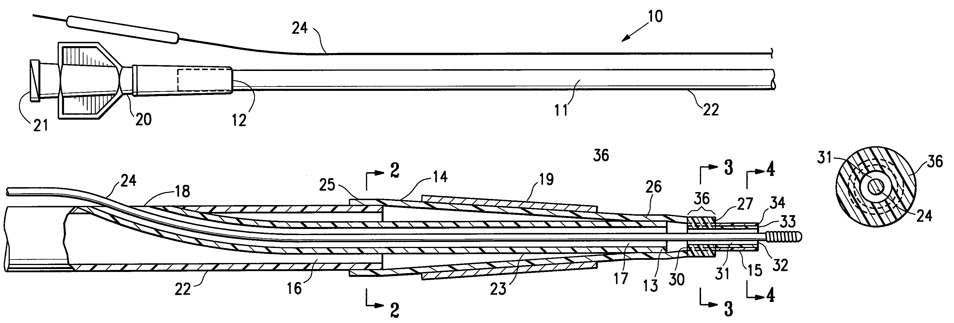
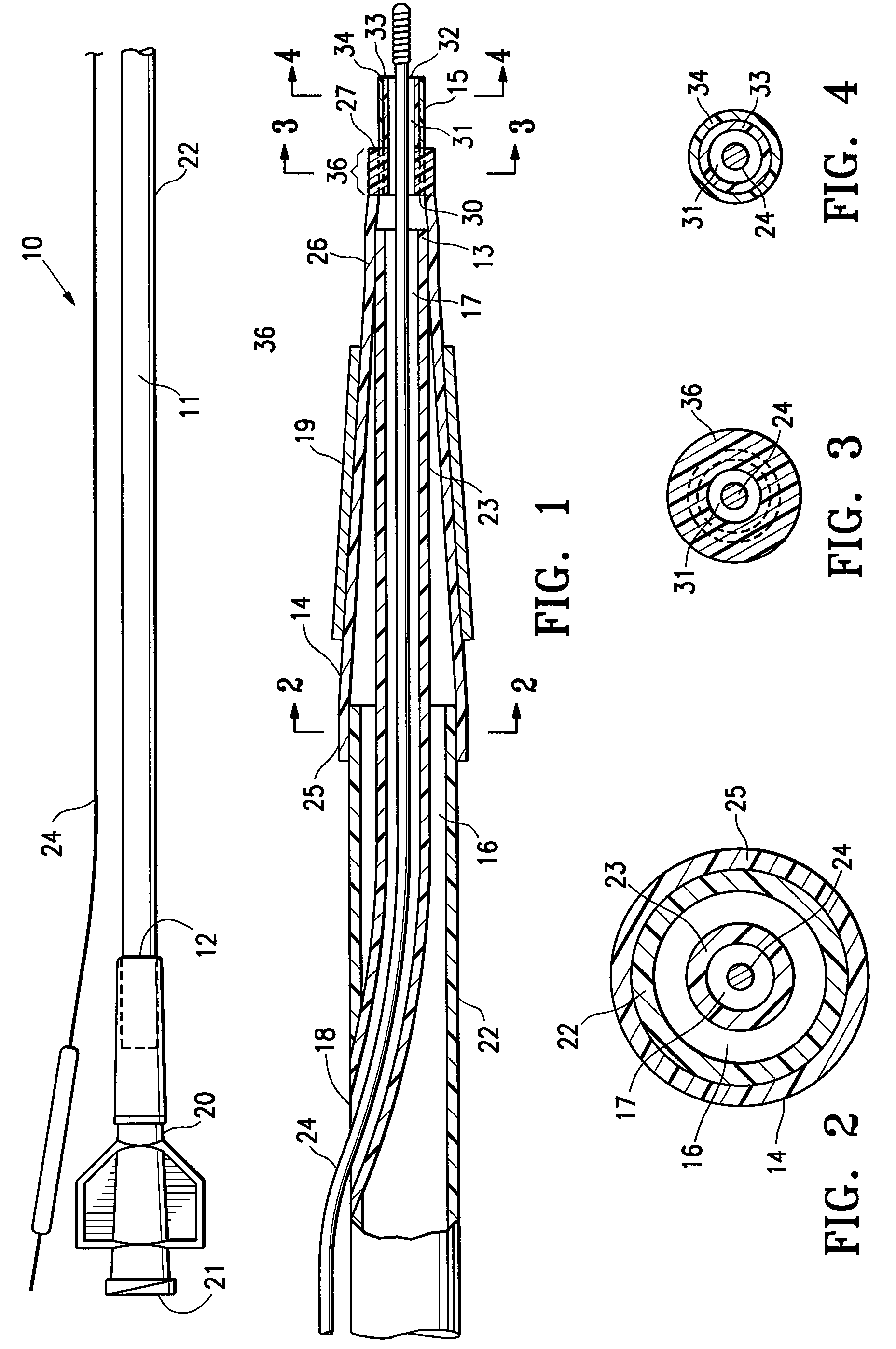
[0019]FIG. 1 illustrates a stent delivery balloon catheter 10 embodying features of the invention, generally comprising an elongated catheter shaft 11 having a proximal end 12 (within a strain relief / proximal adapter), a distal end 13, a proximal shaft section, a distal shaft section, an inflatable balloon 14 on the distal shaft section, and a distal tip 15 at a distal end of the catheter 10. The catheter shaft 11 has an inflation lumen 16 and a guidewire lumen 17. In the illustrated embodiment, the catheter 10 is a rapid exchange-type catheter with the guidewire lumen 17 extending along the distal shaft section to a guidewire proximal port 18 spaced distally from the proximal end 12 of the catheter shaft. At the proximal end 12, the shaft connects to strain relief tubing and a proximal adapter 20. The proximal adapter 20 has a port 21 in fluid communication with the inflation lumen 16 of the catheter shaft 11 and configured for connecting to a fluid source (not shown) for inflating...


PUM

PropertyMeasurementUnit
flexural modulusaaaaaaaaaa
total lengthaaaaaaaaaa
thicknessaaaaaaaaaa

Abstract

A balloon catheter having a soft distal tip member having a non-tacky inner (liner) layer material and a soft flexible outer layer material, with both materials being readily thermally bondable to the catheter balloon.

Description

CROSS-REFERENCES TO RELATED APPLICATIONS[0001]NoneBACKGROUND OF THE INVENTION[0002]This invention relates generally to catheters, and particularly intravascular catheters for use in percutaneous transluminal coronary angioplasty (PTCA) or for the delivery of stents.[0003]In percutaneous transluminal coronary angioplasty (PTCA) procedures a guiding catheter is advanced in the patient's vasculature until the distal tip of the guiding catheter is seated in the ostium of a desired coronary artery. A guidewire is first advanced out of the distal end of the guiding catheter into the patient's coronary artery until the distal end of the guidewire crosses a lesion to be dilated. A dilatation catheter, having an inflatable balloon on the distal portion thereof, is advanced into the patient's coronary anatomy over the previously introduced guidewire until the balloon of the dilatation catheter is properly positioned across the lesion. Once properly positioned, the dilatation balloon is inflat...

Claims


Application Information

Patent Timeline
Patent Type & Authority Patents(United States)
IPC IPC(8): A61M29/00
CPCA61M25/001A61M25/0069A61M25/10A61M25/0045A61M25/008A61M25/1025A61M25/0068A61M25/104A61M2025/0081A61M2025/1093Y10T156/1005A61M2025/0047
Inventor LEE, JEONG S.WANTINK, KENNETH L.
Owner ABBOTT CARDIOVASCULAR
Why Eureka
Try Eureka