
Apparatus equipped with metallic manganese anode for generating power from voltage gradients at the sediment-water interface

a technology of metallic manganese anodes and anodes, which is applied in the direction of indirect fuel cells, non-aqueous electrolyte cells, cell components, etc., can solve the problem of limiting the period of time over which a sensor or instrument can operate, and achieve the effect of reducing at least one species

Inactive Publication Date: 2009-06-23
THE UNITED STATES OF AMERICA AS REPRESENTED BY THE SECRETARY OF THE NAVY
View PDF19 Cites 9 Cited by
  • Summary
  • Abstract
  • Description
  • Claims
  • Application Information

AI Technical Summary

Benefits of technology

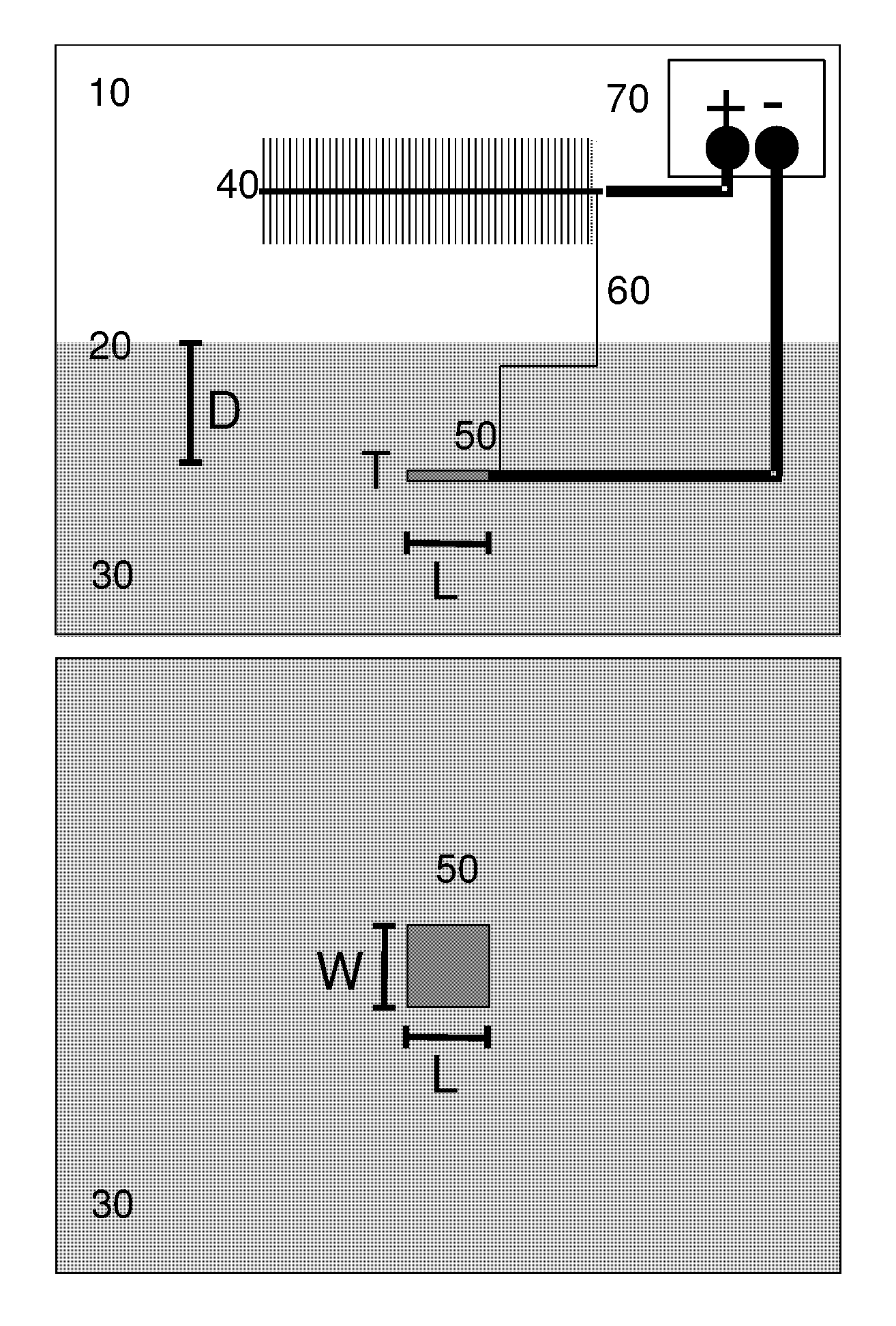
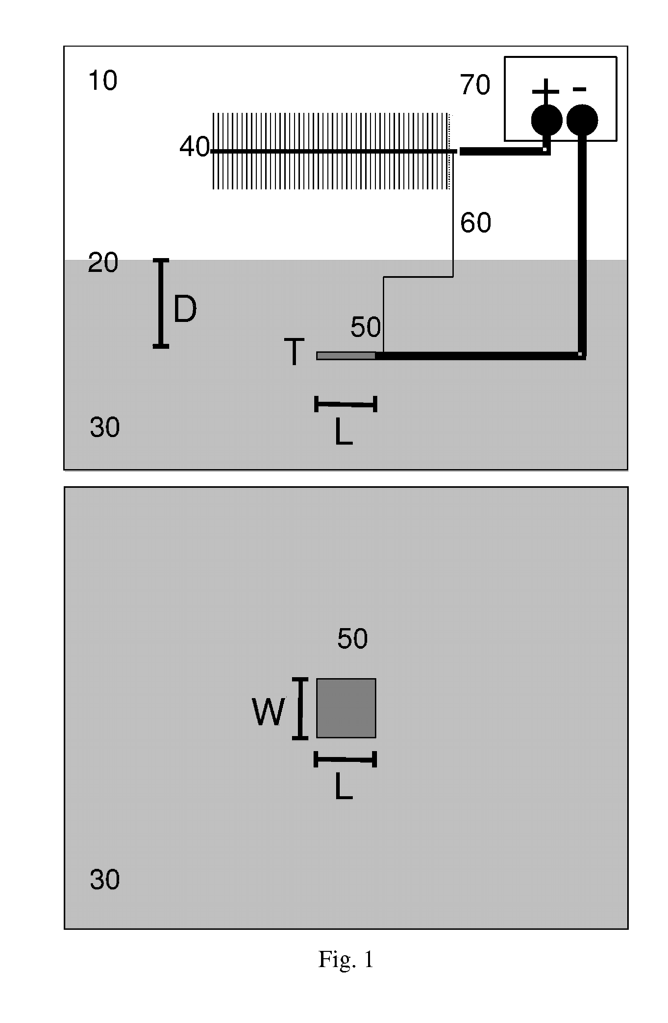
[0005]The invention comprises an apparatus comprising: an anode comprising metallic manganese; a cathode capable of reducing at least one species found in marine water; and a rig coupled to the anode and the cathode capable of maintaining the anode below a marine sediment surface and maintaining the cathode above the marine sediment surface.
[0006]The invention further comprises a method of generating power comprising: positioning in marine sediment an anode comprising metallic manganese; positioning in marine water a cathode capable of reducing at least one species found in marine water; and connecting electrical leads between the anode, the cathode, and an electrical load.

Problems solved by technology

The key limitation of battery-based power supplies is depletion (i.e., exhaustion of energy content), which limits the period of time over which a sensor or instrument can operate.
Many others (present or envisioned) operate unattended for longer periods of time, and are fundamentally limited by battery depletion requiring costly and resource intensive retrieval and redeployment cycles.

Method used


Image

  • Apparatus equipped with metallic manganese anode for generating power from voltage gradients at the sediment-water interface
  • Apparatus equipped with metallic manganese anode for generating power from voltage gradients at the sediment-water interface
  • Apparatus equipped with metallic manganese anode for generating power from voltage gradients at the sediment-water interface

Examples


example 1

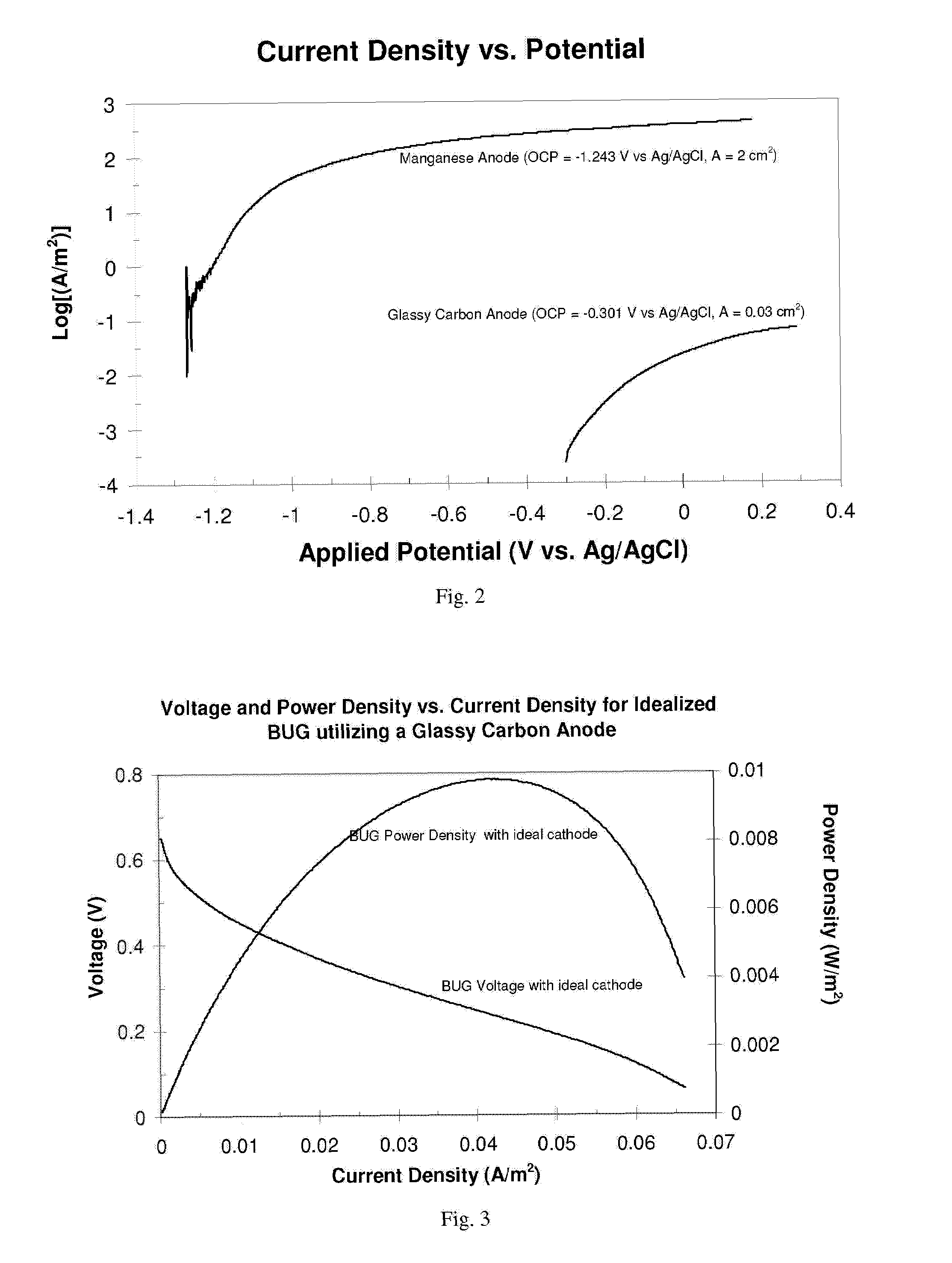
[0033]Comparison of Mn to graphite (current density)—FIG. 2 depicts a comparison of current density vs. potential characterization of a manganese anode and a glassy carbon (graphite) anode. In the context of BUG anodes (i.e., non-Mn), this characterization reflects expected performance of BUGs in which each anode is matched with an ideal cathode (i.e., a graphite cathode of infinite size), so that sustained current, voltage, and power are only limited by the anode. The manganese anode consisted of an ˜1-cm×1-cm square×0.1-cm (2-cm geometric area) of 99.999% manganese flake (Aldrich) with insulated connection to an electrical lead. The glassy carbon electrode consisted of 0.2-cm diameter (0.03-cm2 geometric area) glassy carbon disc purchased and used as received from Bioanalytical Systems, Inc. (BAS). Measurements were conducted in a laboratory in a reconstructed seafloor comprised of sediment and seawater collected from a coastal site near Tuckerton, N.J. Each anode was inserted int...

example 2

[0034]Comparison of Mn to graphite (voltage and power density)—FIGS. 3 and 4 depict characterizations of expected voltage and power density vs. current density for an idealized BUG utilizing a glassy carbon anode (FIG. 3) and a manganese anode (FIG. 4). These characterizations are based on the current density vs. potential characterization for each anode depicted in FIG. 3. In FIG. 4, the expected performance of a BUG is represented that consists of the manganese anode in FIG. 3 matched with an ideal cathode (i.e., a graphite cathode of infinite size so that sustained current, voltage, and power are only limited by the anode. Here, voltage of the BUG is determined by subtraction of the anode applied voltage from 0.35 V vs. Ag / AgCl, sat. KCl (i.e., the typical open circuit voltage of BUG graphite cathode). Power density is the product of voltage and current density. Here the voltage and power density vs. current density properties of the idealized BUG utilizing a glassy carbon anode ...

example 3

[0035]Prolonged discharge of Mn anode—FIGS. 5 and 6 depict data generated by prolonged discharge of a for a 1-cm2 geometric area Mn anode discharged for >24 hours in marine sediment collected form Tuckerton, N.J. site, at constant voltage, corresponding to highest power density when matched with an ideal cathode (Voltage=−0.45 V vs. Ag / AgCl, sat. KCl, FIG. 5), and at lower current density (Voltage=−1.1 vs. Ag / AgCl, sat. KCl, FIG. 6). These figures demonstrate sustainable power density at different voltages (and therefore current densities) over the duration of measurements. Left axis indicates measured current normalized by anode geometric area yielding current density. Right axis indicates expected power density by a BUG utilizing a Mn anode with open circuit voltage (OCP) of −1.2 V vs. Ag / AgCl, sat. KCl reference electrode in overlying seawater and ideal cathode (large enough so that all BUG voltage drop occurs at anode). In FIG. 5, 0.8 V corresponds to BUG voltage expected for ma...


PUM

PropertyMeasurementUnit
areaaaaaaaaaaa
voltageaaaaaaaaaa
areaaaaaaaaaaa

Abstract

An apparatus having a metallic manganese anode; a cathode capable of reducing at least one species found in marine water; and a rig coupled to the anode and the cathode capable of maintaining the anode below a marine sediment surface and maintaining the cathode above marine the sediment surface. A method of generating power by: positioning in marine sediment a metallic manganese anode; positioning in marine water a cathode capable of reducing at least one species found in marine water; and connecting electrical leads between the anode, the cathode, and an electrical load.

Description

CROSS REFERENCE TO RELATED APPLICATIONS[0001]This application claims priority to U.S. Provisional Patent Application No. 60 / 712,612, filed on Aug. 30, 2005 and incorporated herein by reference.FIELD OF THE INVENTION[0002]The invention relates generally to fuel cells for use in marine sediment and seawater.DESCRIPTION OF RELATED ART[0003]Typically, marine / oceanographic sensors and instruments deployed in water are powered by batteries. The key limitation of battery-based power supplies is depletion (i.e., exhaustion of energy content), which limits the period of time over which a sensor or instrument can operate. Many marine / oceanographic sensors and instruments deployed in water operate for short periods of time that are easily sustained by batteries. Many others (present or envisioned) operate unattended for longer periods of time, and are fundamentally limited by battery depletion requiring costly and resource intensive retrieval and redeployment cycles. It is widely recognized th...

Claims


Application Information

Patent Timeline
Patent Type & Authority Patents(United States)
IPC IPC(8): H01M2/12H01M4/36H01M6/34H01M8/16
CPCH01M4/38H01M4/90H01M8/16H01M8/20H01M8/22H01M12/04Y02E60/527Y02E60/528Y02E60/50Y02E60/10
Inventor TENDER, LEONARDLOWY, DANIEL
Owner THE UNITED STATES OF AMERICA AS REPRESENTED BY THE SECRETARY OF THE NAVY
Learn More