
Hybrid antennas with directly fed antenna slots for handheld electronic devices

a handheld electronic device and hybrid antenna technology, applied in separate antenna unit combinations, resonant antennas, radiating element structural forms, etc., can solve the problem of difficult design of compact antennas that cover all frequencies of interest, and achieve the effect of broadening the bandwidth of a given communication band

Active Publication Date: 2009-06-23
APPLE INC
View PDF14 Cites 92 Cited by
  • Summary
  • Abstract
  • Description
  • Claims
  • Application Information

AI Technical Summary

Benefits of technology

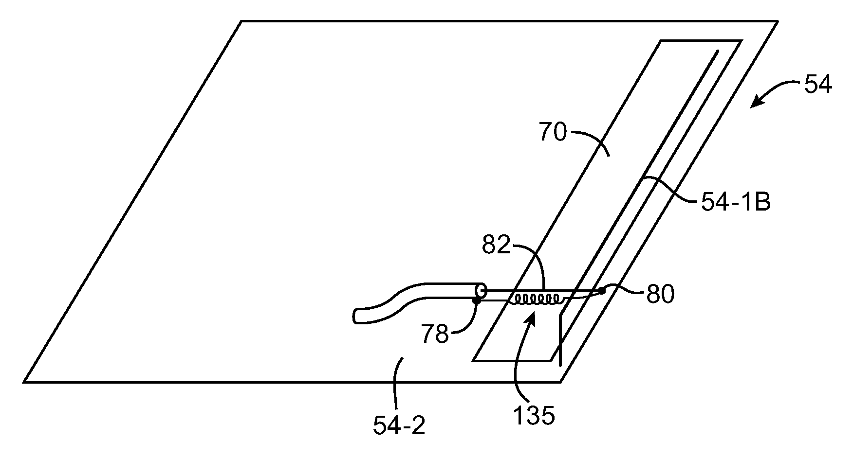
[0009]The slot antenna resonating element may have multiple openings or branches that define multiple associated inner slot perimeters and thereby allow the slot antenna resonating element to resonate at multiple resonant frequencies. The near-field-coupled antenna resonating element may have multiple branches that allow the near-field-coupled antenna resonating element to resonate at multiple frequencies. The resonant peaks associated with the slot antenna resonating element portion of the antenna and the near-field-coupled antenna resonating element portion of the antenna can be configured to nearly or exactly coincide with each other to broadened the bandwidth of a given communications band or can be configured to provide coverage for distinct communications bands. In some configurations, the use of more than one antenna resonating element to transmit and receive radio-frequency signals for a handheld electronic device may make the antenna and handheld electronic device less susceptible to influences from a user's hand position.

Problems solved by technology

Although modern handheld electronic devices often need to function over fairly wide frequency bands or over a number of different communications bands, it is difficult to design a compact antenna that covers all frequencies of interest while satisfying design constraints related to antenna efficiency and immunity to proximity effects.

Method used


Image

  • Hybrid antennas with directly fed antenna slots for handheld electronic devices
  • Hybrid antennas with directly fed antenna slots for handheld electronic devices
  • Hybrid antennas with directly fed antenna slots for handheld electronic devices

Examples


Embodiment Construction

[0037]The present invention relates generally to wireless communications, and more particularly, to wireless electronic devices and antennas for wireless electronic devices.

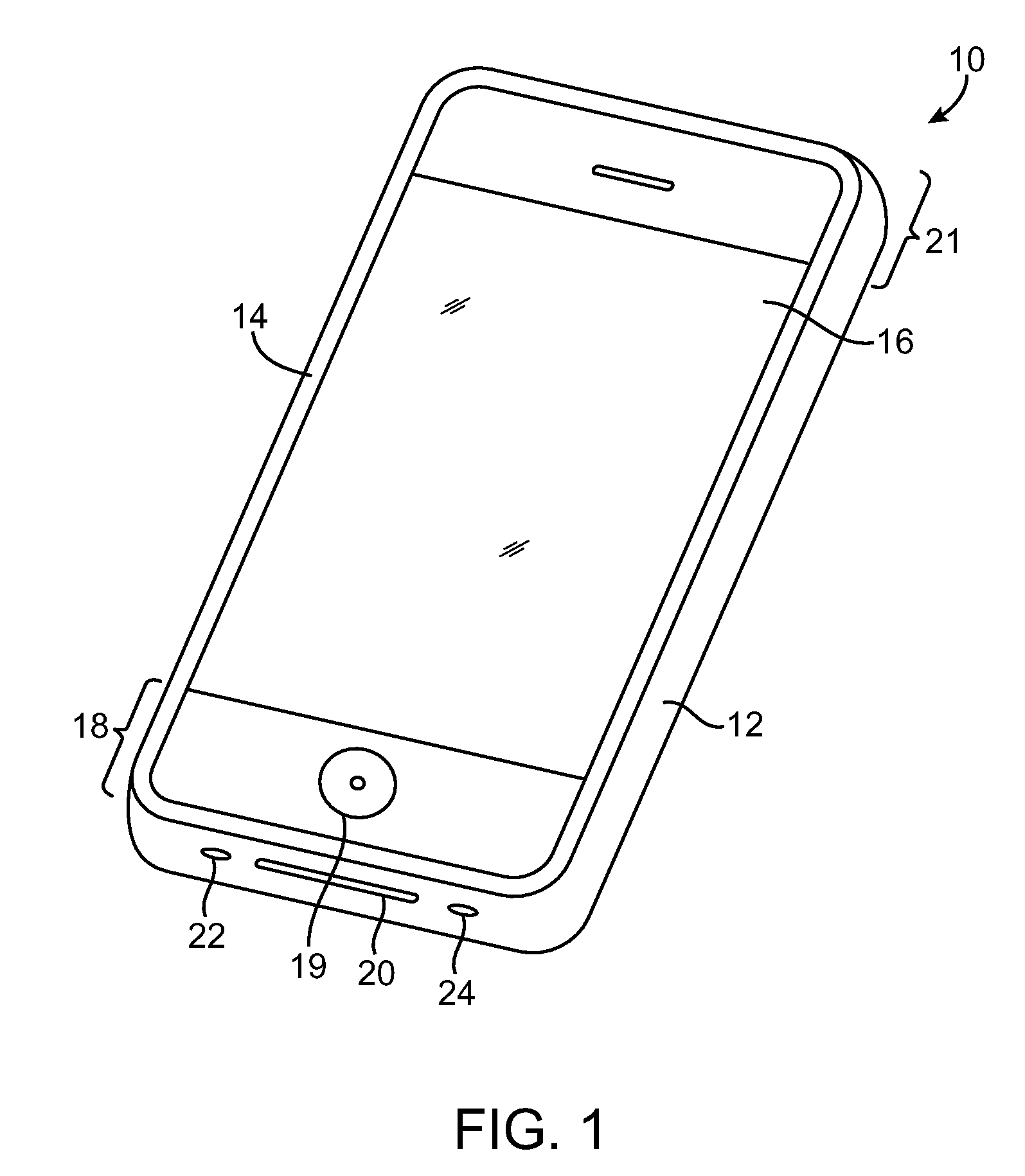
[0038]The wireless electronic devices may be portable electronic devices such as laptop computers or small portable computers of the type that are sometimes referred to as ultraportables. Portable electronic devices may also be somewhat smaller devices. Examples of smaller portable electronic devices include wrist-watch devices, pendant devices, headphone and earpiece devices, and other wearable and miniature devices. With one suitable arrangement, which is sometimes described herein as an example, the portable electronic devices are handheld electronic devices.

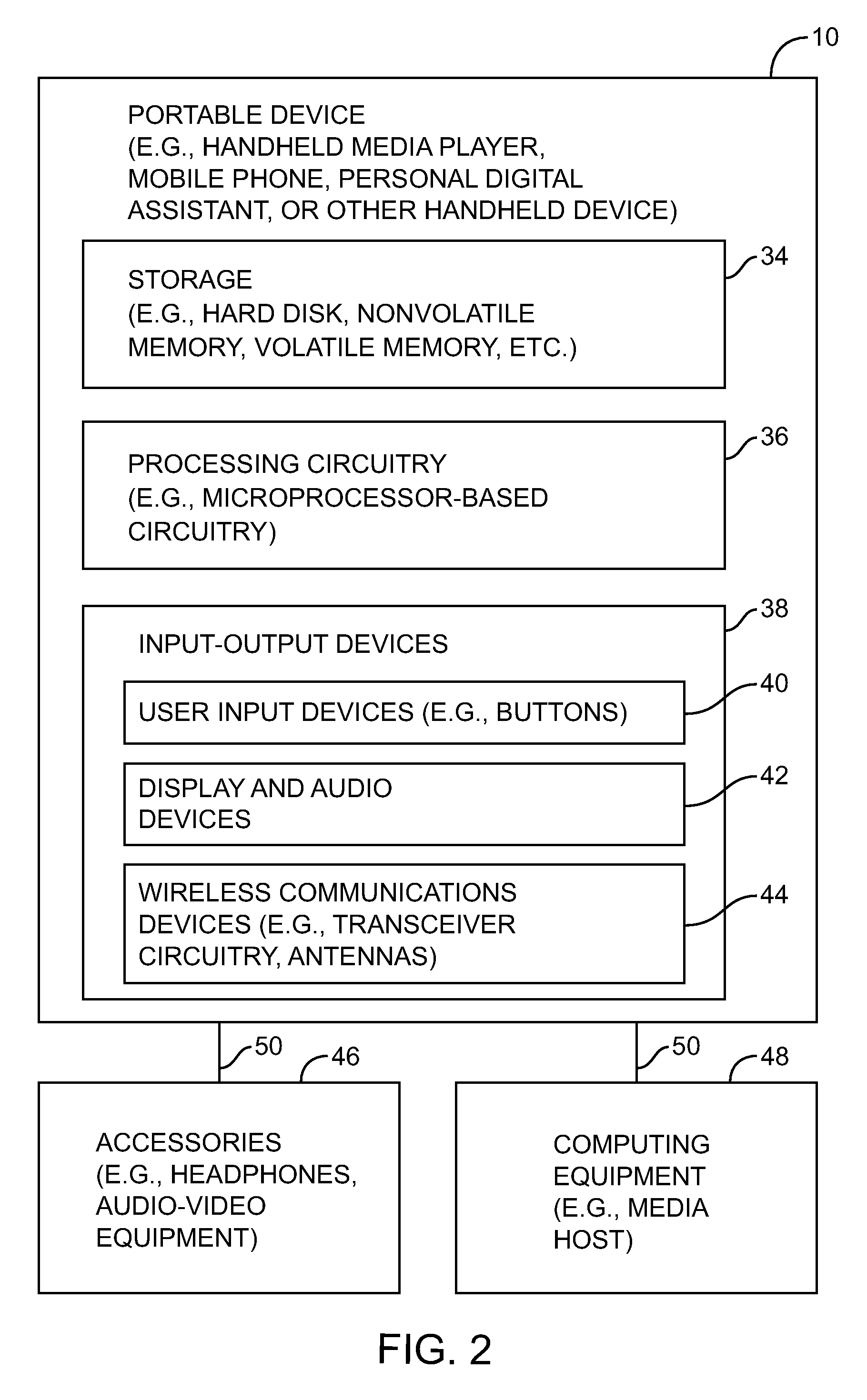
[0039]The handheld devices may be, for example, cellular telephones, media players with wireless communications capabilities, handheld computers (also sometimes called personal digital assistants), remote controllers, global positioning system (GPS) device...


PUM


Abstract

A handheld electronic device is provided that contains wireless communications circuitry. The wireless communications circuitry may include antennas. An antenna in the handheld electronic device may have a ground plane element. A slot antenna resonating element may be formed from an opening in the ground plane element. A near-field-coupled antenna resonating element may be electromagnetically coupled to the slot antenna resonating element through electromagnetic near-field coupling. A transmission line may directly feed the slot antenna resonating element. The transmission line may indirectly feed the near-field-coupled antenna resonating element through the slot antenna resonating element. The slot antenna resonating element may have one or more associated resonant frequencies and the near-field-coupled antenna resonating element may have one or more associated resonant frequencies. The antenna may be configured to cover one or more distinct communications bands.

Description

BACKGROUND[0001]This invention relates generally to wireless communications circuitry, and more particularly, to wireless communications circuitry for handheld electronic devices.[0002]Handheld electronic devices are becoming increasingly popular. Examples of handheld devices include handheld computers, cellular telephones, media players, and hybrid devices that include the functionality of multiple devices of this type.[0003]Due in part to their mobile nature, handheld electronic devices are often provided with wireless communications capabilities. Handheld electronic devices may use long-range wireless communications to communicate with wireless base stations. For example, cellular telephones may communicate using cellular telephone bands at 850 MHz, 900 MHz, 1800 MHz, and 1900 MHz. Handheld electronic devices may also use short-range wireless communications links. For example, handheld electronic devices may communicate using the Wi-Fi® (IEEE 802.11) band at 2.4 GHz and the Bluet...

Claims


Application Information

Patent Timeline
Patent Type & Authority Patents(United States)
IPC IPC(8): H01Q1/24
CPCH01Q1/243H01Q1/52H01Q5/392H01Q21/30H01Q5/371H01Q13/10
Inventor ZHANG, ZHIJUNHILL, ROBERT J.SCHLUB, ROBERT W.ZAVALA, JUANCABALLERO, RUBEN
Owner APPLE INC
Learn More