System and method for transmission of video signals using multiple channels

a video signal and communication network technology, applied in the field of communication systems, can solve the problems of low-bit-rate transmission of digital imagery and video, and high probability of error in wireless traffic channels such as traffic channels b>46/b>, so as to facilitate the transmission of video frames over multiple channels and effectively accommodate transmission latency

Active Publication Date: 2009-06-23
GENERAL DYNAMICS MISSION SYST INC
View PDF10 Cites 56 Cited by
  • Summary
  • Abstract
  • Description
  • Claims
  • Application Information

AI Technical Summary

Benefits of technology

[0016]Accordingly, it is an advantage of the present invention that a system and method are provided for satellite-based transmission of video signals using multiple wireless channels.
[0017]It is another advantage of the present invention that a system and method are provided that are resilient to packet loss on any individual wireless channel, as well as to loss of any individual wireless channel.
[0018]Another advantage of the present invention is that a system and method are provided for transmission of video signals that can effectively accommodate transmission latency within a satellite-based communication network.
[0019]Yet another advantage of the present invention is that implementation of the system and method are transparent to the existing infrastructure of the satellite-based communication network.
[0020]The above and other advantages of the present invention are carried out in one form by a method of facilitating transmission of video frames over multiple channels in a wireless communication network. The method calls for generating, for each of the video frames, frame data representative of the video frame, and transforming the frame data to obtain transform coefficients of the frame data. The method further calls for assembling quadtrees of the transform coefficients, each of the quadtrees including a group of the transform coefficients associated with an equivalent spatial location in the frame data. The quadtrees are separately coded to form coded quadtree coefficient groups, and the coded quadtree coefficient groups are distributed among the multiple channels for transmission.
[0021]The above and other advantages of the present invention are carried out in another form by a coder / decoder system for facilitating transmission of video frames over multiple channels in a wireless communication network. The system includes an input for receiving each of the video frames, and a processor in communication with the input for generating frame data representative of each video frame. A wavelet transformer is in communication with the processor for transforming the frame data to obtain wavelet coefficients of the frame data. A quadtree-based compressor receives the wavelet coefficients and assembles quadtrees of the wavelet coefficients, each of the quadtrees including a group of wavelet coefficients associated with an equivalent spatial location in the frame data. A coder separately codes the quadtrees to form coded quadtree coefficient groups, and an output interface, in communication with the coder, receives the coded quadtree coefficient groups. The output interface assigns the coded quadtree coefficient groups to the multiple channels such that adjacent portions of the frame data will be transmitted over different ones of the multiple channels.

Problems solved by technology

In a vast number of regions throughout the Earth, there exists little or no infrastructure capable of effective communication of digital imagery and video.
Unfortunately, transmission of digital imagery and video over low-bit-rate, wireless links, such as traffic channels 46 is extremely problematic due to limited channel bandwidth.
In addition to the limited available bandwidth, wireless traffic channels 46 have a high probability of error due to latency, fading effects, and / or channel drop out.
Conventional video coders, such as video coder 48, are incapable of effectively interfacing with satellite-based communication networks to facilitate the transmission of digital imagery and real-time video under the conditions of limited bandwidth, latency, fading effects, and / or channel drop out.

Method used


Image

  • System and method for transmission of video signals using multiple channels
  • System and method for transmission of video signals using multiple channels
  • System and method for transmission of video signals using multiple channels

Examples


Embodiment Construction

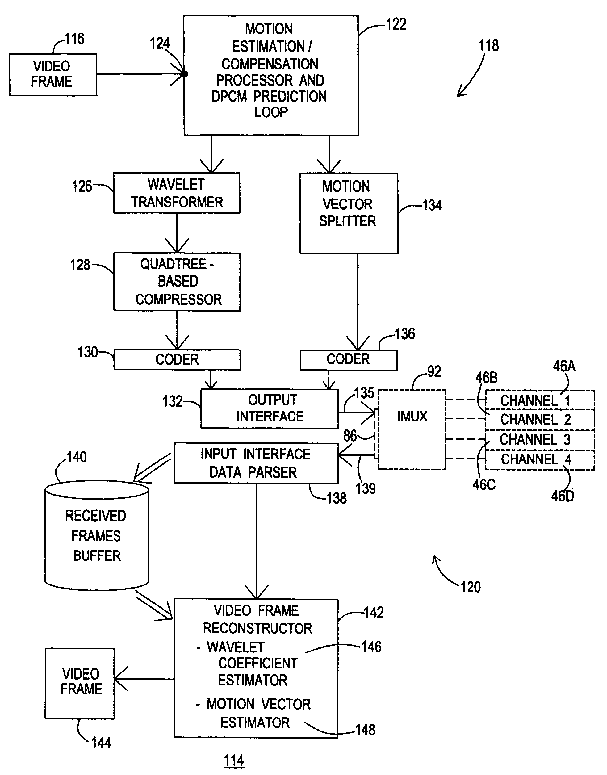
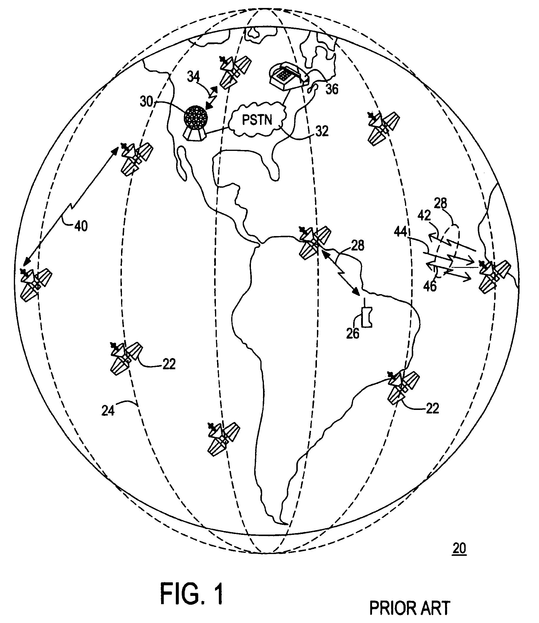
[0050]Referring to FIGS. 1 and 4, FIG. 4 shows a simplified diagram of a portion of satellite-based communication network 20 in which inverse multiplexer (IMUX) systems 64 are employed. IMUX systems 64 are adapted for use with a satellite-based communication network, such as network 20, exemplifying the Iridium® commercial system. IMUX systems 64 extend the capability of voice-optimized wireless traffic channels 46, within network 20, for the transmission of data and video, without the addition of terrestrial or airborne network infrastructure. The present invention is adapted for use with IMUX systems 64 for effectively utilizing wireless channels for the transmission of video signals. For clarity of understanding, IMUX systems 64 will be discussed below.

[0051]Although the present invention is described in terms of its use with the Iridium® commercial system, the present invention is not limited to such a use. Rather, the present invention is applicable to land-based wired or wirel...


PUM


Abstract

In a communication network (20), a video encoder/decoder system (114) and an encoding method (150) facilitate transmission of video frames (116) over multiple low-data-rate channels (46). Frame data (204) is generated for each video frame (116). The frame data (204) is transformed (172) to obtain transform coefficients (212), which are assembled (174) into quadtrees (216) and separately coded (178). In addition, motion vectors (166) are split into coding blocks (188) and separately coded (190). The quadtrees (126) and the motion vectors (166) are independently distributed among the multiple channels (46) for transmission. A decoding method (360) facilitates error resilient reception of transform coefficient packets (222) and motion vector packets (244) so that lost transform coefficients (374) and/or lost motion vectors (384) can be estimated at a receiving video encoder/decoder system (114) to reconstruct a received video frames 144.

Description

RELATED INVENTIONS[0001]The present invention claims priority under 35 U.S.C. §119(e) to: “Video Coding and Transmission Over Multiple Very Low Bit-Rate Channels,” U.S. Provisional Patent Application Ser. No. 60 / 463,573, filed 16 Apr. 2003, which is incorporated by reference herein.[0002]The present invention is related to “System And Method For Satellite-Based Transmission Of Signals Using Multiple Channels,” by Glen P Abousleman, U.S. patent application Ser. No. 10 / 404,791, filed 1 Apr. 2003, which is incorporated by reference herein.TECHNICAL FIELD OF THE INVENTION[0003]The present invention relates to the field of communication systems. More specifically, the present invention relates to a system and method for the transmission of video signals over a communication network using multiple channels.BACKGROUND OF THE INVENTION[0004]Technological advances in recent years have made it easier for individuals and groups in geographically disperse societies to be interconnected through ...

Claims


Application Information

Patent Timeline
Patent Type & Authority Patents(United States)
IPC IPC(8): H04N11/04H04J99/00H04N7/24
CPCH04N21/238H04N21/2385H04N21/6131H04N21/6143H04N21/631H04N21/845
Inventor TYLDESLEY, KATHERINE S.ABOUSLEMAN, GLEN P.KARAM, LINA J.
Owner GENERAL DYNAMICS MISSION SYST INC
Why Eureka
Try Eureka