
Thread cutting tap and a method of its manufacture

a technology of thread cutting and thread, which is applied in the direction of forging/pressing/hammering equipment, forging/hammering/pressing machines, wood boring tools, etc., can solve the problems of chip-breaking members, low cutting speed, and accumulation of chips

Inactive Publication Date: 2009-06-30
SANDVIK INTELLECTUAL PROPERTY AB
View PDF31 Cites 37 Cited by
  • Summary
  • Abstract
  • Description
  • Claims
  • Application Information

AI Technical Summary

Benefits of technology

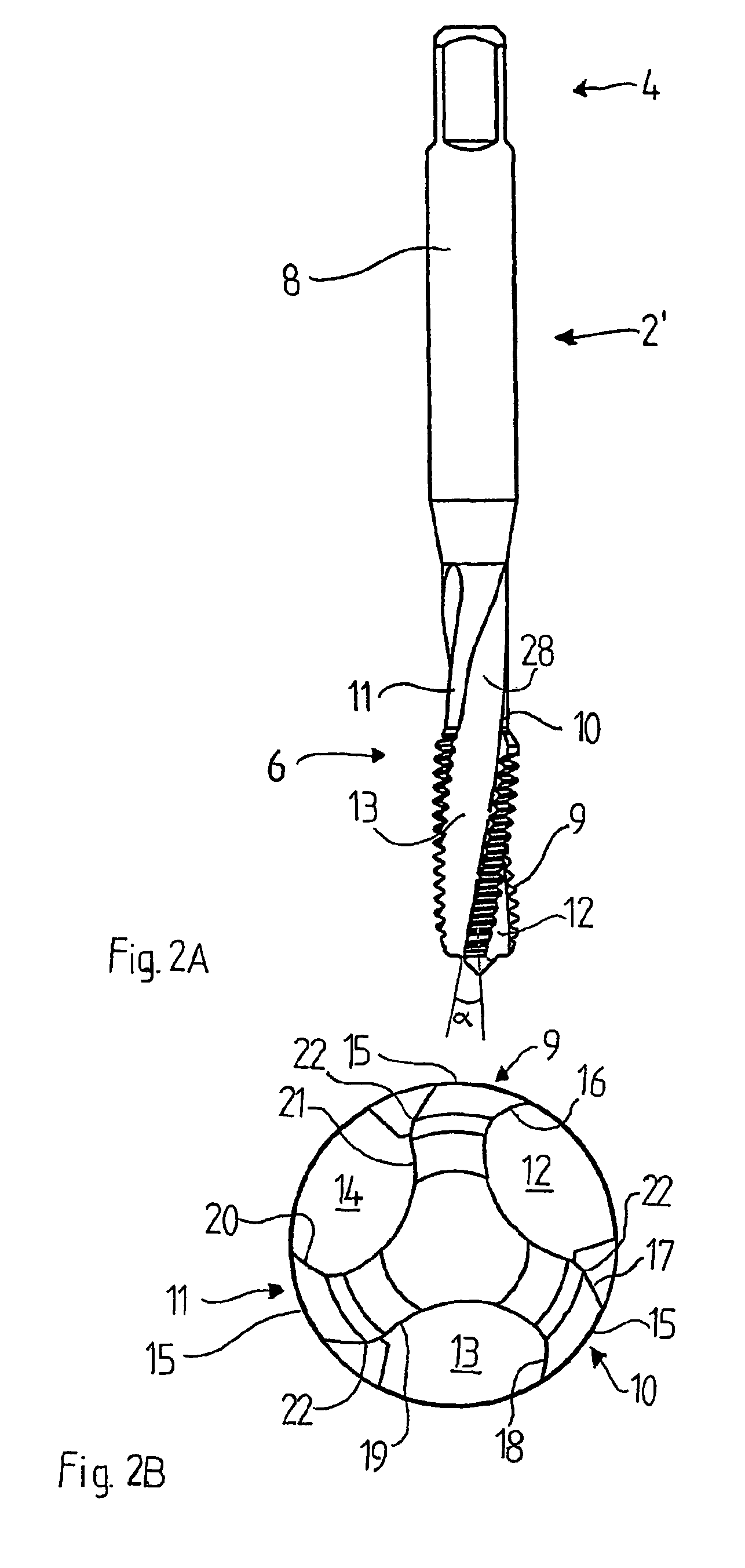
The invention is a thread cutting tap with improved chip handling properties. The tap has chip removal flutes that are at least partly helically shaped, which allows for high cutting speeds without chip entanglement or accumulation. The tap can be used in blind or through holes. The chip removal flutes can be straight or helically shaped, and the angle between the tap and the flutes can range from 10°-50° or 1°-15° depending on the desired chip removal direction. The tap can also have a coating with a friction reducing coating to improve chip transport and wear resistance. The technical effects of the invention include improved chip handling, high cutting speeds, and better chip removal directionality.

Problems solved by technology

Such flutes are disadvantageous, since the transportation of chips is poor, risking to cause accumulation of chips in the flutes.
It also suffers from the drawback that it can only be used at relatively low cutting speeds.
The chip-breaking member in the form of an indentation is however disadvantageous, because it is only applicable to straight flute taps, as machining of the flank portion for achieving the chip-breaking member is complicated.

Method used


Image

  • Thread cutting tap and a method of its manufacture
  • Thread cutting tap and a method of its manufacture
  • Thread cutting tap and a method of its manufacture

Examples


Embodiment Construction

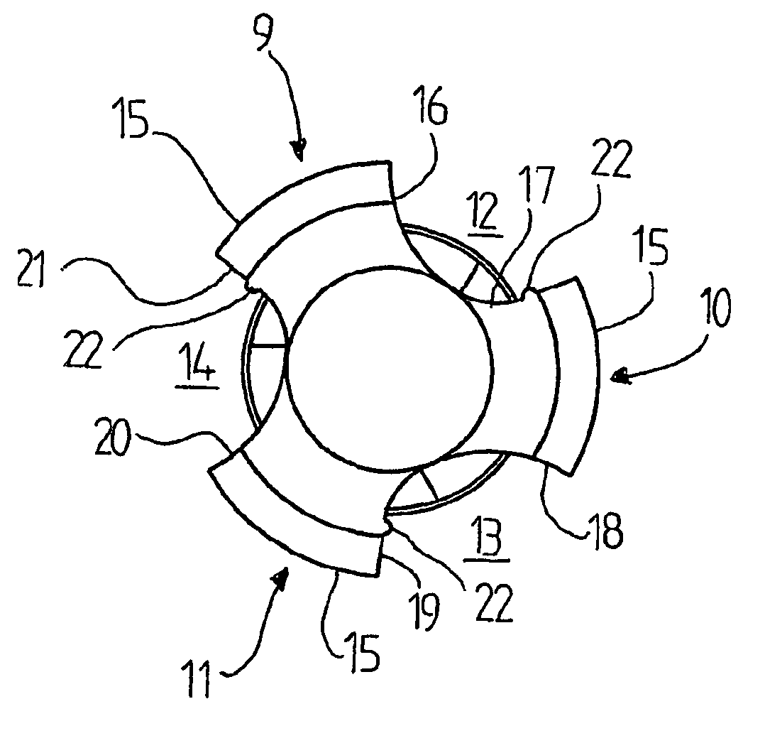
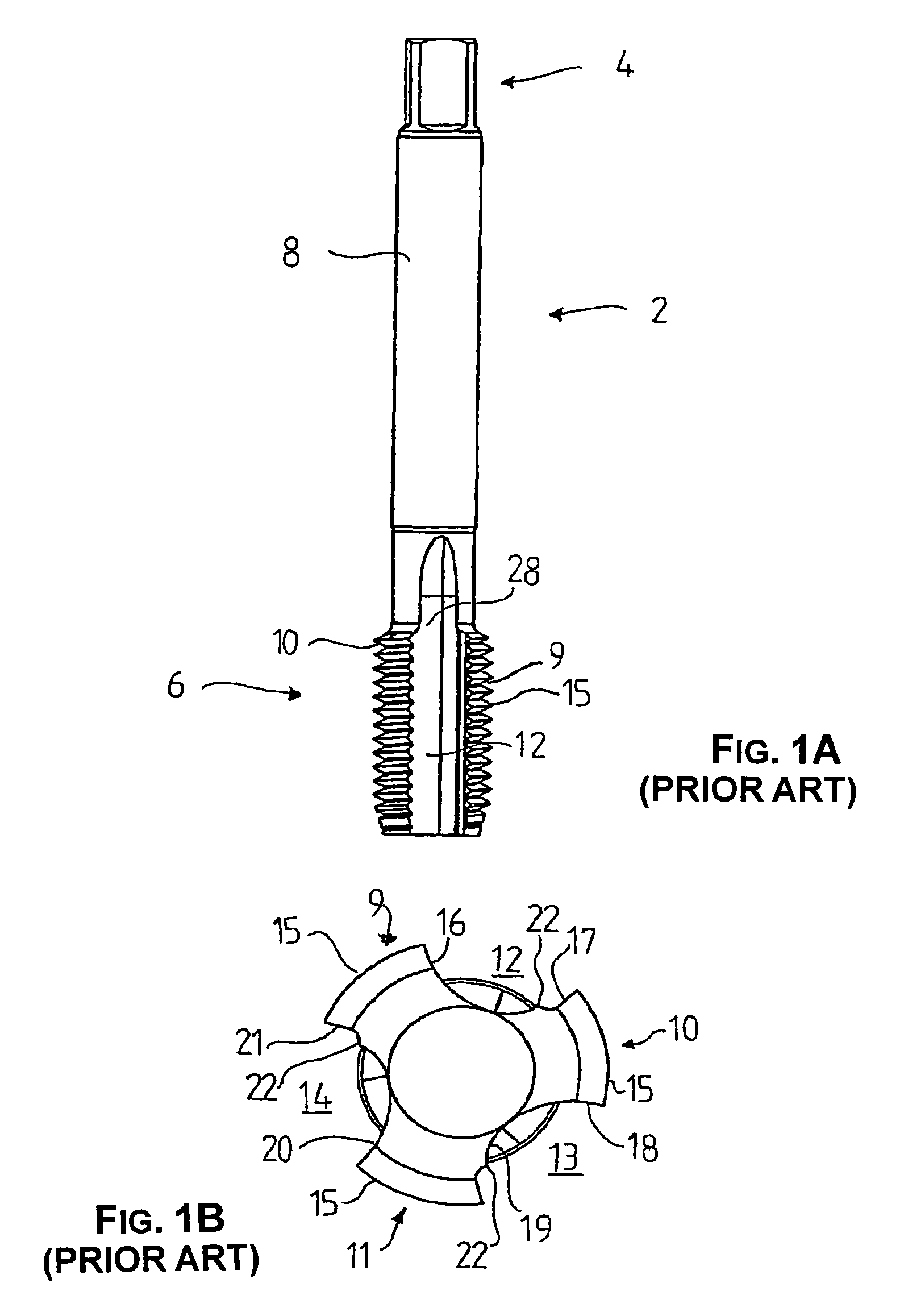
[0028]FIG. 1A is a side elevation of a prior art straight fluted tap 2 comprising an elongated body having a connector portion 4, a threaded portion 6 and an intermediate portion 8. The threaded portion has, in the longitudinal direction of the body, three flanks 9, 10, 11 (FIG. 1B) divided by three straight flutes 12, 13, 14. The peripheral part of the flanks 10 is provided with cutting edges 15. The cutting edges 15 divided by the flutes 12, 13, 14 form together a virtual continuous helical thread. The flute 12 is defined by a side-wall 16 of the flank 9 and a side-wall 17 of the flank 10, the side-wall 17 being interconnected to the side-wall 16. Likewise, the flute 13 is defined by a side-wall 18 of the flank 10 and a side-wall 19 of the flank 11 and the flute 14 is defined by a side-wall 20 of the flank 11 and a side-wall 21 of the flank 9. Furthermore, the side-walls 18 and 19, and the side-walls 20 and 21 are interconnected, respectively.

[0029]Each of the side-walls 16, 18 an...


PUM

PropertyMeasurementUnit
flute angleaaaaaaaaaa

Abstract

A thread cutting tap having a threaded portion for cutting out a thread in a wall of a workpiece opening into which the threaded portion is to be introduced. The threaded portion is provided with at least two cutting edges extending in a circumferential direction of the body. Each cutting edge is an integral peripheral part of a flank portion extending substantially radially from the body. The flank portions define between one another a chip removal flute extending in the longitudinal extension of the body for removal of chips. At least one of the flank portions has a side wall divided into a pair of elongated concave surfaces separated by an elongated ridge constituting a chip-breaking member. The chip removal flutes are at least partly helically shaped.

Description

TECHNICAL BACKGROUND OF THE INVENTION[0001]The present invention relates to a thread cutting tap having an elongated body, comprising at a first end a connector portion adapted to be connected to a tool and at a second end a threaded portion for cutting out a thread in a wall of an opening into which said threaded portion is to be introduced, said threaded portion being provided with at least two cutting edges in the circumferential direction of said body, each of said cutting edges being an integral peripheral part of a flank portion extending substantially radially from the longitudinal extension of said body, said flank portions defining therebetween a chip removal flute in the longitudinal extension of said body for removal of chips cut from said wall, wherein at least one of said flank portions having a side-wall is provided with a chip-breaking member.[0002]It also relates to a method of manufacturing such a thread cutting tap.[0003]A thread cutting tap of this kind is known f...

Claims


Application Information

Patent Timeline
Patent Type & Authority Patents(United States)
IPC IPC(8): B23G5/06B23P15/52
CPCB23G5/06B23P15/52Y10T408/9048Y10T408/9097
Inventor OKNESTAM, MARKUSZIVKOVIC, STEFAN
Owner SANDVIK INTELLECTUAL PROPERTY AB
Learn More