
Hidden mold transfer assembly

Inactive Publication Date: 2009-06-30
HONDA MOTOR CO LTD
View PDF22 Cites 11 Cited by
  • Summary
  • Abstract
  • Description
  • Claims
  • Application Information

AI Technical Summary

Benefits of technology

[0018]It is an object of the present invention to provide an assembly and strategy for receiving, moving, and supporting one or more molds to or from an injection m

Problems solved by technology

Although necessary in certain instances, storing molds on the floor is generally undesirable.
First, that practice can lead to injury if someone trips or stumbles upon the molds.
Placing molds on the floor can lead to contamination of the molds.
Third, molds frequently contain coatings or residual amounts of liquids such as oils, water, and various chemical agents used in the molding process.
Storing such molds on the floor can promote collection of these liquids and agent(s) on the floor and into the work environment, which may create safety hazards and violate local safety codes.
Fourth, storing molds on the floor uses valuable floor space.
This may be particularly undesirable in many industrial and manufacturing facilities.
Although mold carts provide numerous features and benefits, they are not always used.
The cost of such carts may be prohibitive for some businesses.
The layout or physical configuration of certain operations may also be a barrier to their use.
Moreover, for relatively large molds, such as those used to produce large parts or components, the significant size and mass of the molds typically precludes the use of mold carts.
The tiered frame is provided with upper and lower storage sections which are said to retain one or more “injection molding machine units.” Although satisfactory for small-scale applications, the tiered frame is insufficient for supporting the massive molds typically used in injection molding large parts or components.
Although providing a space-saving function, it is doubtful that the structure could support massive and heavy molds typically used in injection molding of large parts.
In addition, neither of the structures described in the '026 patent to Maru et al. nor the '860 patent to Pierik et al. provide any means for moving the molds from the press to a location remote from the press, and vice versa.
And so, neither of the structures described in the noted patents provide any solution or assistance in changing or replacing the molds.
Although the '371 patent to Nickley and the '491 patent to Nitschke et al. provide similar mechanisms and strategies for mold changing, each approach still requires an assembly that consumes significant amounts of floor space around the press.
Furthermore, it is questionable whether such mechanisms could be used in conjunction with massive molds employed in the production of large injection molded parts.

Method used


Image

  • Hidden mold transfer assembly
  • Hidden mold transfer assembly
  • Hidden mold transfer assembly

Examples


Embodiment Construction

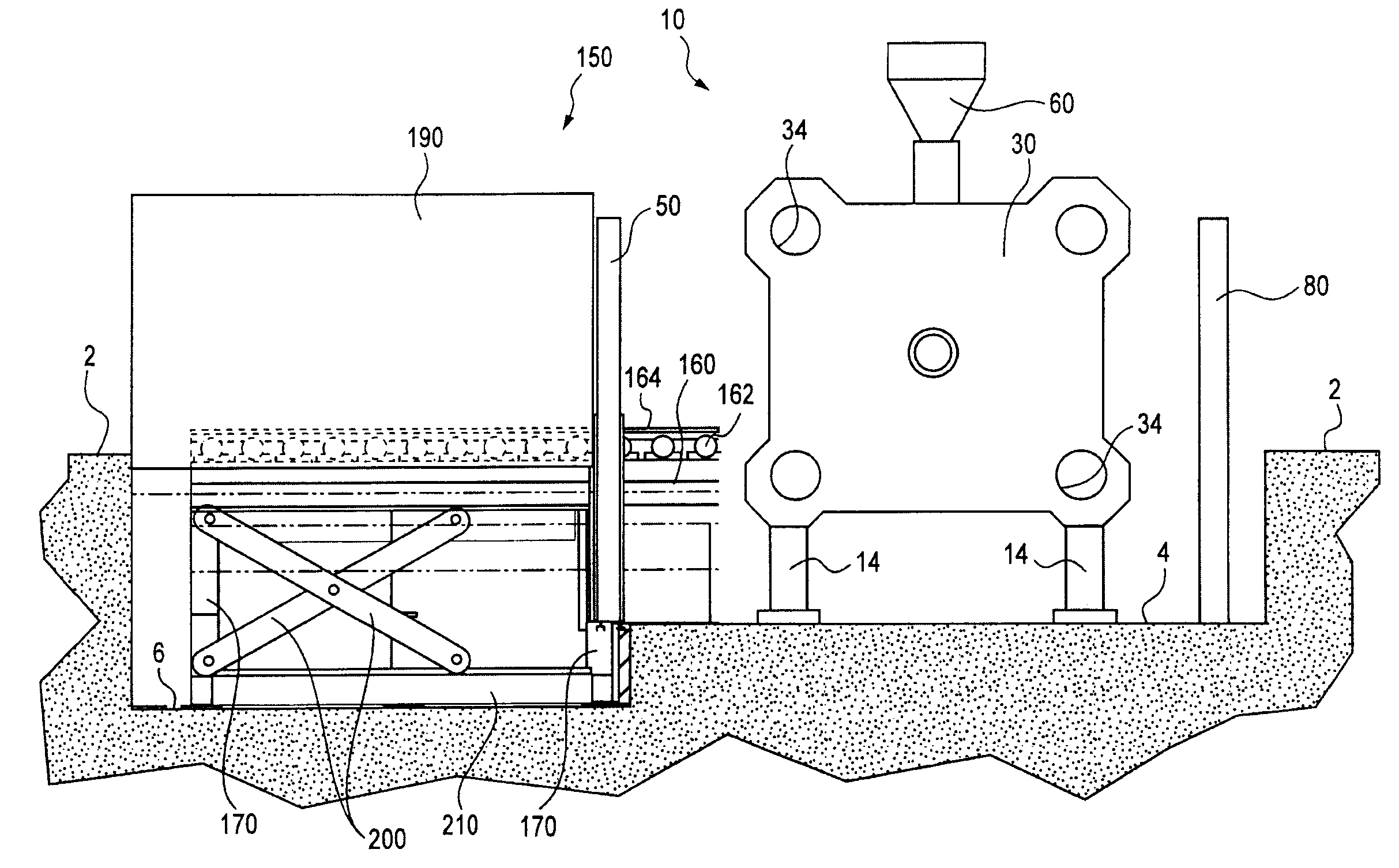
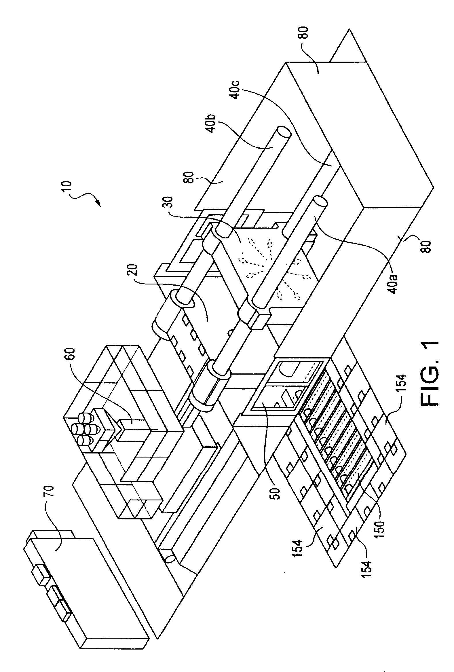
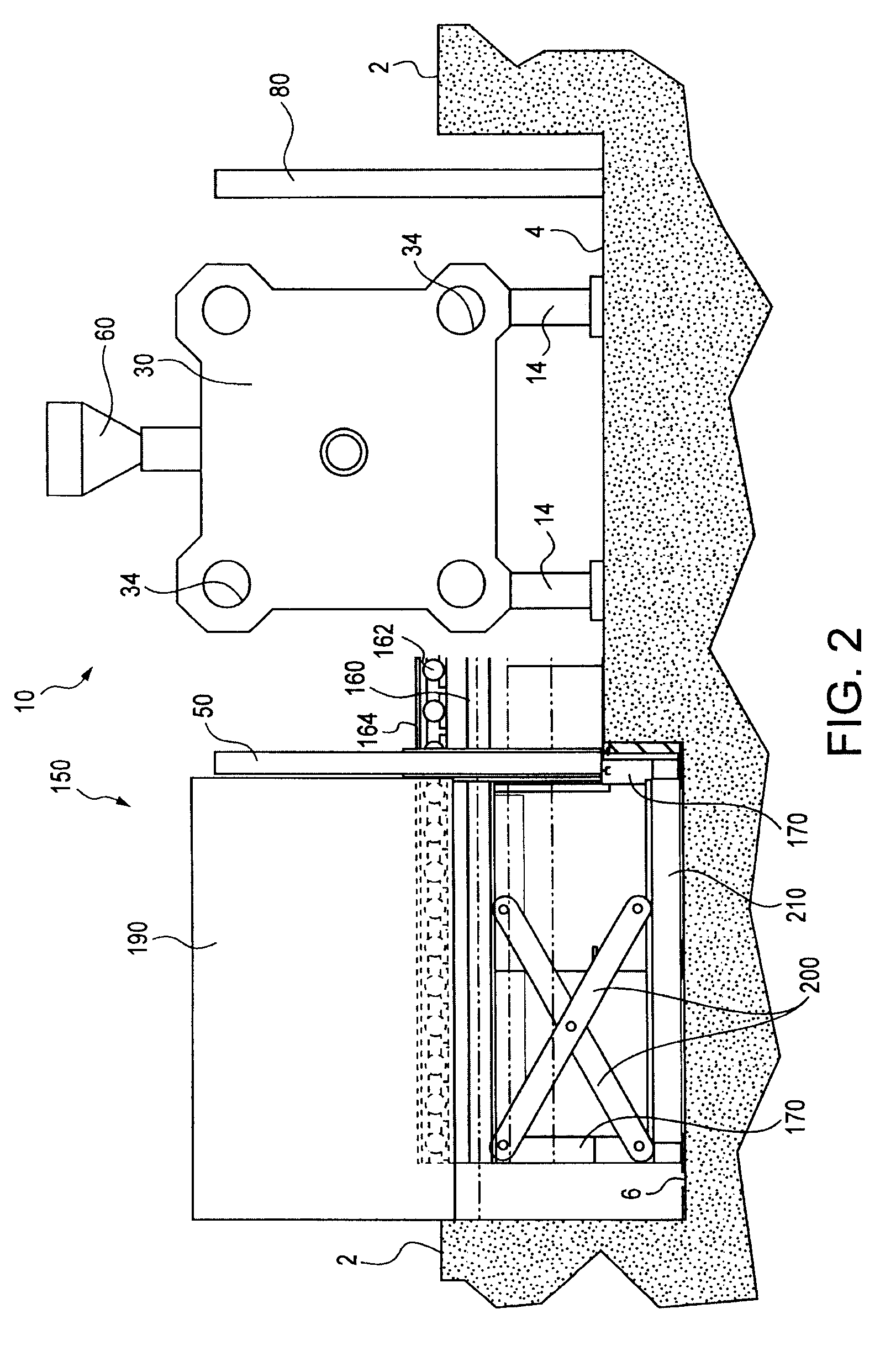
[0042]As described herein, the present invention provides a hidden mold transfer assembly that is preferably at least partially disposed within a recessed pit or region alongside an injection molding press. The preferred embodiment mold transfer assembly is positionable between two states, a retracted or stowed state in which the assembly is disposed entirely below floor level, and an extended state in which the assembly is in a raised position and able to receive a mold set or other mold components from the interior of the press. Numerous other features and variations of the present invention assembly and related methods are described herein.

[0043]The injection molding presses with which the present invention hidden mold transfer assembly can be used, are generally of the larger, hydraulic or hybrid, i.e. electric and hydraulic, type. Hydraulic presses in the range of from 200 tons to 6,000 tons, or more, are typically those with which the preferred embodiment mold transfer assembl...


PUM

PropertyMeasurementUnit
Sizeaaaaaaaaaa
Heightaaaaaaaaaa

Abstract

A mold transfer assembly is described that upon placement or construction along a region of an injection molding press, readily receives and retains mold(s) used in the press, and when not in use can be stored below the floor. The mold transfer assembly includes a mold receiving member that is positionable between an extended or raised state, at which the member is at a position, orientation, and height suitable for receiving a mold or set of molds from the press, and a retracted position at which the member is positioned under the floor. This configuration and positioning ability enables greater amounts of floor space to be used when the mold transfer assembly is not in use. Also described is a molding platen having a selectively positionable mold support ledge that enables molds of different sizes to be used in a single press.

Description

BACKGROUND OF THE INVENTION[0001]The presently disclosed embodiments are directed to the field of manufacturing and molding, and particularly, to injection molding equipment and processes for producing relatively large parts or components.[0002]Large, industrial presses use injection molds, tools or dies that are pressed together under high pressure in one or more operations to receive molding material to thereby form a part or component. Typically, injection molds comprise a set of molds, typically two, that when engaged together, define a hollow interior into which molding material is injected under very high pressure to form parts having a shape or configuration corresponding to the hollow interior defined by the molds.[0003]Injection molds are typically interchangeable, so that different molds can be used in a single press. This enables manufacture of a wide array of different parts from a single press, by merely interchanging the molds in the press. In addition, molds are often...

Claims


Application Information

Patent Timeline
IPC IPC(8): B29C45/17B29C33/30
CPCB29C45/1744B29C45/1756
Inventor HUGHES, ALANWOJNIAK, CHAD
Owner HONDA MOTOR CO LTD
Learn More