Matching network characterization using variable impedance analysis

a technology of impedance analysis and matching network, which is applied in the direction of impedence matching network, semiconductor/solid-state device testing/measurement, instruments, etc., can solve the problems of reducing the accuracy of power measurement, increasing the inaccuracy of resistance calculation, and building a complex

Inactive Publication Date: 2009-06-30
APPLIED MATERIALS INC
View PDF6 Cites 6 Cited by
  • Summary
  • Abstract
  • Description
  • Claims
  • Application Information

AI Technical Summary

Benefits of technology

[0039]A further benefit of the above-described measurement method of the invention is the capability to estimate the ESR (ESR) at any tune point of the matching network. The importance of this benefit is demonstrated in the plot of FIG. 4, which outlines the significant change in ESR with respect to frequency for a variable shunt, frequency tuned matching network. The plot of FIG. 4 clearly illustrates that ESR changes with respect to shunt element variation (the element that is typically used to dial in the real portion of the load impedance so as to achieve the 50Ω load resistance) can be approximated by first order by looking at any departure from the expected linear response during the 1 / I2 versus RLOAD analysis. If any significant non-linearity is observed, a smaller RLOAD range, centered at the load impedance for that particular match condition, can provide an approximation of RMW at that point and allow for a two dimensional map across match tune space. For example, any observed non-linearity can be approximated by reducing the range of real impedance over which the data is acquired, such that a piece-wise linear approximation of the non-linear response can thereby be established.

Problems solved by technology

However, drawbacks to this computational method include: a) only one match set point can be tested; b) the matching network typically cannot tune to a zero resistance load condition, which results in a mismatch condition that reduces the accuracy of the power measurement (and therefore increases the inaccuracy of the resistance calculation); and c) the matching network requires an accurate measurement of RF current at the match output for proper operation, which is not provided by conventional configurations.
However, building a complex, purely reactive load is very difficult.
Therefore, unaccounted for losses in the surrogate load will overestimate the power dissipation in the matching network, resulting in higher than actual resistance approximations for conventional matching networks of this configuration.

Method used


Image

  • Matching network characterization using variable impedance analysis
  • Matching network characterization using variable impedance analysis
  • Matching network characterization using variable impedance analysis

Examples


Embodiment Construction

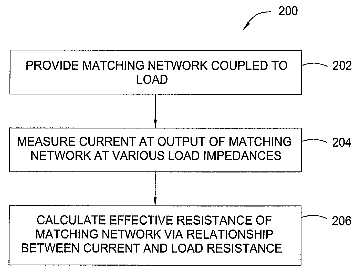
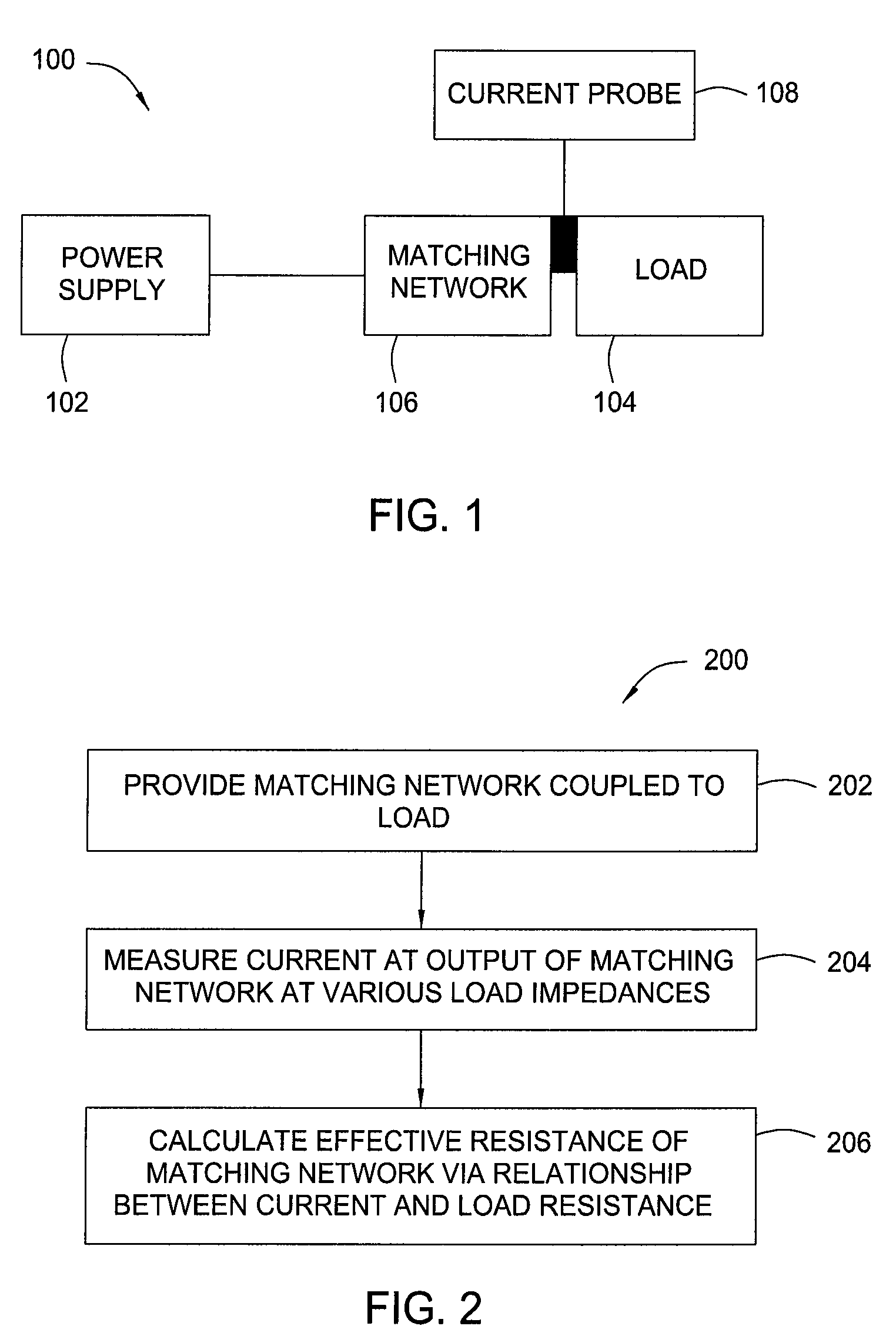
[0016]The present invention generally provides a matching network analysis technique that operates to accurately approximate an equivalent series resistance (ESR) for the matching network through a series of matching network output extrapolations at various load resistances. The approximation of the ESR of the matching network allows for approximation of the matching network loss (also referred to as the insertion loss of the matching network) due to the series resistance at all points within the match tune space. The present invention also generally provides for matching networks characterized by methods in accordance with the present invention.

[0017]FIG. 1 illustrates a general block diagram of a system 100 suitable for characterizing a matching network in accordance with embodiments of the present invention. The system 100 generally includes a power supply 102 in communication with a load 104 through a matching network 106. A probe 108 is generally provided for measuring current ...


PUM

PropertyMeasurementUnit
complex impedanceaaaaaaaaaa
total impedanceaaaaaaaaaa
resistanceaaaaaaaaaa

Abstract

Embodiments of a method of calculating the equivalent series resistance of a matching network using variable impedance analysis and matching networks analyzed using the same are provided herein. In one embodiment, a method of calculating the equivalent series resistance of a matching network includes the steps of connecting the matching network to a load; measuring an output of the matching network over a range of load impedances; and calculating the equivalent series resistance of the matching network based upon a relationship between the measured output and the load resistance. The load may be a surrogate load or may be a plasma formed in a process chamber.

Description

BACKGROUND OF THE INVENTION[0001]1. Field of the Invention[0002]Embodiments of the invention generally relate to matching networks for semiconductor processing systems. More specifically, embodiments of the present invention relate to characterization of matching networks.[0003]2. Description of the Related Art[0004]In plasma-enhanced semiconductor processing systems, such as etch or deposition processing systems, radio frequency (RF) matching networks are used to couple RF power from an RF source having a substantially resistive impedance (e.g., 50 ohms) to a load, which is generally a processing plasma in a process chamber, which has a complex impedance. The matching network operates to match the RF source's impedance to the plasma / load's impedance to efficiently couple the RF power from the source to the plasma.[0005]One type of matching network that is widely used in semiconductor wafer processing systems is a tunable matching network, wherein a series connected frequency-depend...

Claims


Application Information

Patent Timeline
Patent Type & Authority Patents(United States)
IPC IPC(8): G01R31/02
CPCH03H7/38H03H11/28H01L21/02H01L22/00
Inventor SHANNON, STEVEN C.HOFFMAN, DANIEL J.LANE, STEVENMERRY, WALTER R.DINEV, JIVKO
Owner APPLIED MATERIALS INC
Why Eureka
Try Eureka