
Brushless vacuum cleaner

a vacuum cleaner and brushless technology, applied in the field of cleaning equipment, can solve the problems of requiring eventual replacement of brushes, affecting the cleaning effect, and requiring premature replacement of brushes, etc., so as to save the cost of replacing prematurely worn carpets, prolong the life of carpets, and easily clean corner areas of rooms

Inactive Publication Date: 2009-07-07
PINNEY CRAIG A
View PDF19 Cites 8 Cited by
  • Summary
  • Abstract
  • Description
  • Claims
  • Application Information

AI Technical Summary

Benefits of technology

[0020]It is another object of the present invention to provide a new and improved brushless vacuum cleaner that may be easily and efficiently manufactured and marketed.
[0021]An even further object of the present invention is to provide a new and improved brushless vacuum cleaner that has a low cost of manufacture with regard to both materials and labor, and which accordingly is then susceptible of low prices of sale to the consuming public, thereby making such a brushless vacuum cleaner economically available to the buying public.
[0023]Even still another object of the present invention is to provide a brushless vacuum cleaner that uses pulsed air flow to agitate the dirt and debris from the surface to be cleaned. This reduces the wear and tear on floor coverings, such as carpet, that is caused by conventional beater brushes, thereby extending the life of the carpet and saving the cost of replacing prematurely worn carpet.
[0024]Yet another object of the present invention is to provide a brushless vacuum cleaner that provides air injectors at the front left corner that are angled inward and downward. This allows the user to more easily clean corner areas of a room with the same vacuuming motion used in the rest of the room, saving the user a considerable amount of time and effort.
[0025]Still yet another object of the present invention is to provide a brushless vacuum cleaner that agitates debris with a pulsed air flow as opposed to a beater brush. This prevents premature wear to the vacuum cleaner, saving the user the time and expense of repeatedly replacing the beater brush for efficient cleaning.
[0026]Lastly, it is an object of the present invention to provide a new and improved brushless vacuum cleaner that provides an extension of air injectors on the side of the base unit. This allows the user to clean a wider swath with each vacuuming motion and provides a narrow extension that can be used in tight areas, significantly reducing the amount of time and effort the user must expend during cleaning.

Problems solved by technology

However, beater brushes inflict wear on surfaces over time and can cause premature replacement of floor coverings such as carpet.
The brushes themselves also suffer wear and require eventual replacement to perform at an acceptable level.
However, the Keller '861 device uses a fluid for cleaning purposes which would not be suitable for frequent use in cleaning carpets or other fiber based flooring materials.
Additionally, the heat discharged by the Keller '861 vacuum system would cause premature wear on carpets and other flooring materials.
'861 device returns some of the particulate matter to the surface being cleaned; therefore, it would not be useful for cleaning of residential or commercial flooring.
'861 device contains a filtering mechanism which would increase the complexity and, thus, the cost of the device over other vacuum type floor cleaners.
However, the Turnbull '649 device would be difficult for use in cleaning corner areas of the room since the secondary air outlet would direct pressurized air away from the apparatus, thus scattering debris away from the air collection stream.
Furthermore, the plenum and duct formation is a rigid construction that does not allow the user to vertically adjust the unit for ease of use or storage purposes.
'574 device on carpeted surfaces could cause premature wear on the carpet.
However, the Coathupe '667 device would be difficult to move across a surface since it does not provide wheels or another arrangement on the bottom of the device for ease of movement.
This could cause difficulty in breathing, especially for individuals with asthma or allergies.
'430 device employs a beater brush which could cause premature wear and damage to the floor cover being cleaned.
While the above-described devices fulfill their respective, particular objectives and requirements, the aforementioned patents do not describe a floor cleaning device that uses air agitation in multiple directions to loosen debris for collection via an intake plenum in the device, thus allowing the user to effectively clean not only the flat surface but also the corners of a room.
'574 devices use a fluid for cleaning purposes and would not be suitable for frequent use in cleaning carpets or other fiber based flooring materials.
'574 or Keller '861 device on carpeted surfaces could cause premature wear of the carpet due to the high velocity fluid streams used by the Thrash, Jr.
'430 device could also cause premature wear of the floor covering due to the use of a beater brush for disloding debris.
'861 device returns some of the particulate matter to the surface being cleaned; therefore, it would not be useful for cleaning of residential or commercial flooring.
'430 devices would not be advantageous for cleaning the corners of a room.
The rigid construction of the plenum and duct of the Turnbull '649 device does not allow the user to vertically adjust the unit for ease of use or storage purposes.
The Coathupe '667 device would be difficult to move since no wheels are provided on the bottom of the device.
'861 device contains a filtering mechanism which would increase the complexity and, thus, the cost of the device over other vacuum type floor cleaners.

Method used


Image

  • Brushless vacuum cleaner
  • Brushless vacuum cleaner
  • Brushless vacuum cleaner

Examples


Embodiment Construction

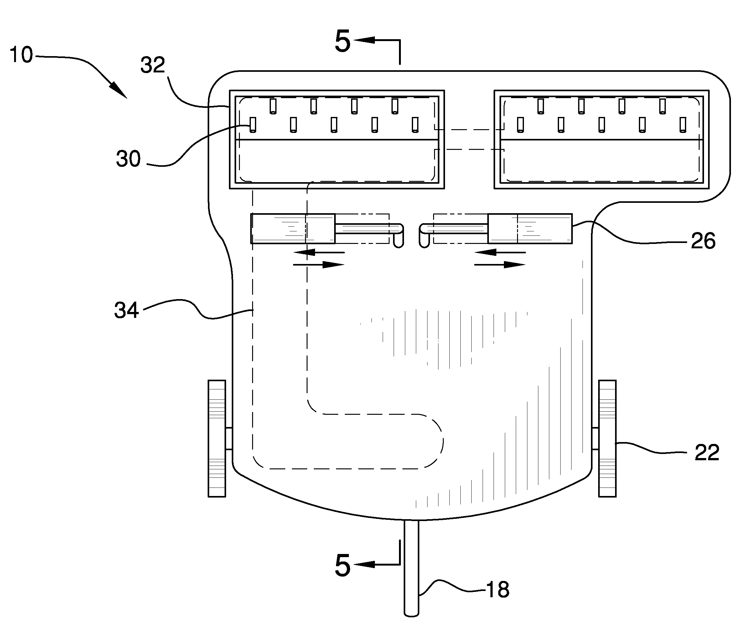
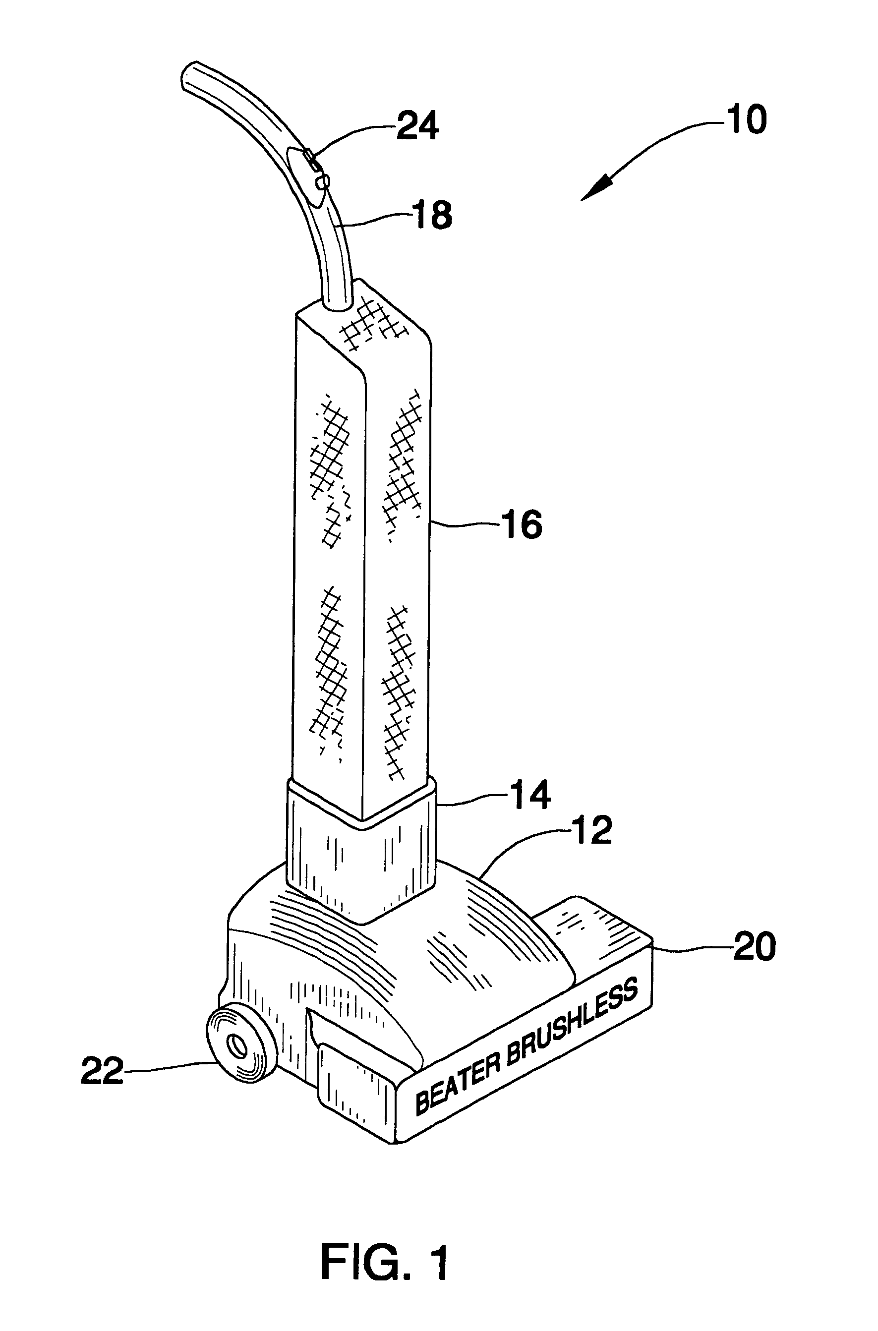
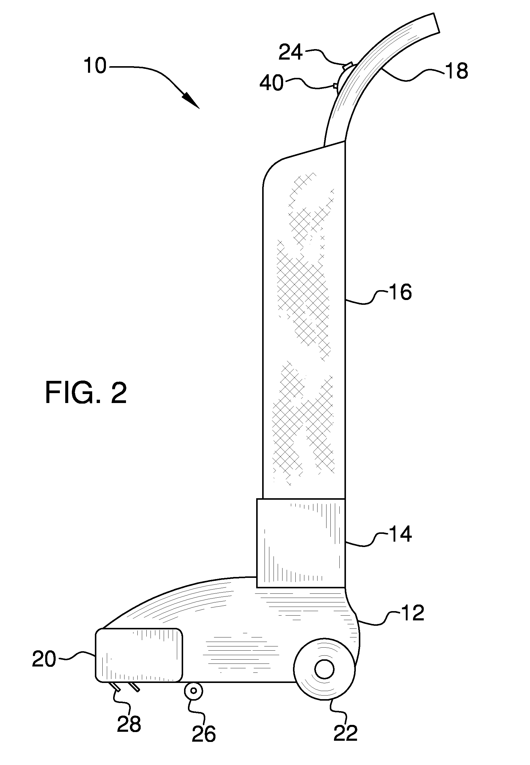
[0035]Referring now to the drawings, and particularly to FIGS. 1-5, a preferred embodiment of the brushless vacuum cleaner of the present invention is shown and generally designated by the reference numeral 10.

[0036]In FIG. 1, a new and improved brushless vacuum cleaner 10 of the present invention for cleaning a carpet with pulsed air flow for agitation, thereby reducing the wear on a carpet caused by beater brushes in conventional vacuums, is illustrated and will be described. More particularly, the brushless vacuum cleaner 10 would feature conventional components used to produce traditional upright vacuum cleaners; however, this appliance would use air pulsation created by an electric air pump to agitate the dirt and debris from carpeting and other flooring surfaces. The brushless vacuum cleaner 10 has a base unit 12 upon which is mounted an air pump case 14. A collection unit 16 with an attached handle 18 extends upward from the air pump case 14. The base unit 12 features a recta...


PUM


Abstract

The brushless vacuum cleaner is an electrical cleaning device that would feature conventional components from traditional upright vacuum cleaners but would use forced air to agitate debris from the surface to be cleaned. The brushless vacuum cleaner would consist of a base unit with multiple air injectors on the bottom, a pump case located on top of the base unit, a collection unit extending upward from the pump case, a vacuum chamber connecting the bottom of the base unit to the collection unit, and a handle that features various control buttons. The pump case would contain an electrical motor which would operate a dual-cycle agitator responsible for pulsing air flow through alternating air injectors on every other cycle. This system would replace the beater brush found on conventional upright vacuum cleaners, thus creating less wear and tear to carpeting and prolonging the life of the carpet.

Description

BACKGROUND OF THE INVENTION[0001]1. Field of the Invention[0002]The present invention relates to a cleaning apparatus for use in connection with vacuuming carpets and other flooring. The brushless vacuum cleaner has particular utility in connection with cleaning a carpet with pulsed air flow for agitation, thereby reducing the wear on a carpet caused by beater brushes in conventional vacuums.[0003]2. Description of the Prior Art[0004]Conventional vacuum cleaners make use of vacuum pressure to draw air and debris adjacent to the vacuum cleaner head into a collection device. Many different forms of vacuum cleaner heads have been developed in the past to aid the debris collection effort. Beater brushes or bars are typical examples of these cleaner heads. A beater brush is used to agitate an area of the surface to be cleaned in an attempt to loosen debris that might not otherwise be susceptible to being lifted by the suction force of the vacuum cleaner. However, beater brushes inflict w...

Claims


Application Information

Patent Timeline
Patent Type & Authority Patents(United States)
IPC IPC(8): A47L5/14A47L5/00
CPCA47L5/28A47L9/0072A47L9/08
Inventor PINNEY, CRAIG A.
Owner PINNEY CRAIG A
Learn More