Apparatus for enhancing hobby servo performance

a technology for enhancing the performance of hobby servos, applied in the direction of motor/generator/converter stoppers, dynamo-electric converter control, manufacturing tools, etc., can solve the problems of mechanical alteration, limited rotation of hobby servo shafts, and the ability to produce a relatively limited amount of torque power, so as to enhance the operational performance of a servo motor

Active Publication Date: 2009-07-14
ROBOTZONE
View PDF9 Cites 20 Cited by
  • Summary
  • Abstract
  • Description
  • Claims
  • Application Information

AI Technical Summary

Benefits of technology

[0008]Embodiments of an independent and modular apparatus are disclosed for enhancing the operational performance of a servo motor. Embodiments include a frame member having a servo motor and a rotatable shaft mounted therein. The output shaft of the servo motor and the rotatable shaft are displaced from one another. Means are incorporated for translating rotational motion from the output shaft to the rotatable shaft so as to enable a torque or rotational capacity for the rotatable shaft that is greater than that of the servo output shaft. Further means are incorporated to enable proportional control of the rotatable shaft even when the output shaft of the servo is rotated beyond its intended range of rotation and / or torque.

Problems solved by technology

Rotation of the hobby servo shaft is limited typically by one or more internal mechanical stops.
It is also typically true that the output shaft of a hobby servo is capable of producing a relatively limited amount of torque power.
It is true, however, that some applications require a servo having torque power and / or a rotational capacity that is beyond the capability of a typical hobby servo.
However, this solution requires mechanical alteration that often only works for some types of servos.
Rotational control for most hobby servos is limited by the internal potentiometer being utilized to monitor rotation.
The control system of a hacked servo will commonly not be configured to accurately position the servo output shaft too far within the extended range of rotation.
For this reason, it becomes difficult to control rotation once a hobby servo has been adapted for extended rotation.

Method used


Image

  • Apparatus for enhancing hobby servo performance
  • Apparatus for enhancing hobby servo performance
  • Apparatus for enhancing hobby servo performance

Examples


Embodiment Construction

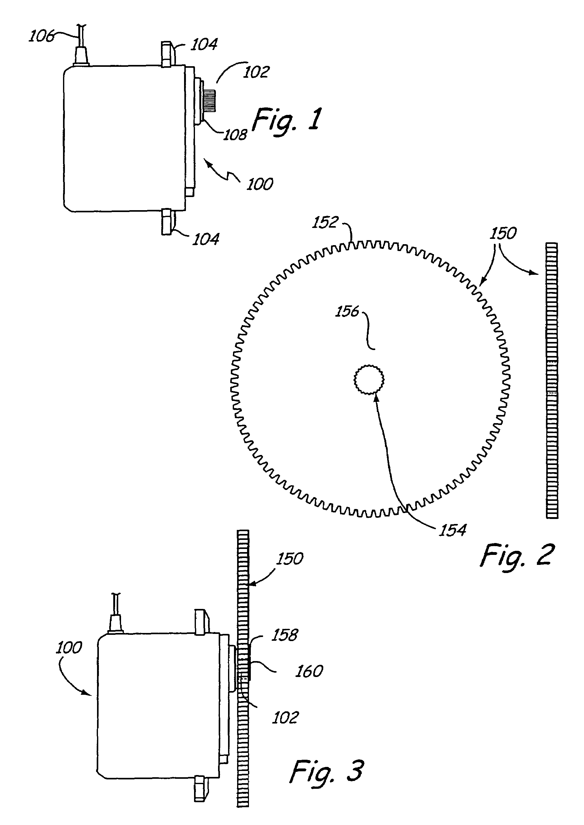
[0020]FIG. 1 is a side view of a hobby servo 100. Servo 100 includes attachment flanges 104. Flanges 104 typically include apertures formed therein for receiving an attachment mechanism (e.g., a screw, bolt, etc). The attachment mechanism is utilized to secure servo 100 within an operative environment. Servo 100 also includes an electrical connection 106 that enables the servo to receive electrical power and / or control signals.

[0021]Servo 100 includes a rotatable output shaft 102 also known as a servo spline. The servo output shaft 102 can be positioned to specific angular positions in accordance with a coded signal received by the servo. It is common that a particular angular position will be maintained as long as a corresponding coded signal exists on an input line. If the coded signal changes, the angular position of the servo output shaft 102 will change accordingly. Control circuits and a potentiometer are typically included within the illustrated outer housing of servo motor 1...


PUM

PropertyMeasurementUnit
Rotationaaaaaaaaaa
anglesaaaaaaaaaa
diameteraaaaaaaaaa

Abstract

A method is disclosed for enhancing the operational capacity of a hobby servo having an internal potentiometer and internal components that limit a rotational capacity. The method comprises disconnecting the internal potentiometer, modifying the internal components to increase the rotational capacity, and connecting the hobby servo to an external potentiometer. The method further comprises operably connecting the hobby servo to an auxiliary shaft that is displaced from the hobby servo, connecting the external potentiometer to the auxiliary shaft, and utilizing feedback from the external potentiometer.

Description

[0001]The present application is based on and claims the benefit of U.S. Provisional Patent Application Ser. No. 60 / 584,288, filed on Jun. 30, 2004, the content of which is hereby incorporated by reference in its entirety.BACKGROUND OF THE INVENTION[0002]The present invention generally pertains to the hobby-mechanical industry. More specifically, the present invention pertains to means for extending the torque and / or rotational capacity of a hobby servo.[0003]A servo motor (a.k.a. simply a “servo”) is a device having a rotatable output shaft. The output shaft can typically be positioned to specific angular positions in accordance with a coded signal received by the servo. It is common that a particular angular position will be maintained as long as a corresponding coded signal exists on an input line. If the coded signal changes, the angular position of the shaft will change accordingly. Control circuits and a potentiometer are typically included within the servo motor casing and ar...

Claims


Application Information

Patent Timeline
Patent Type & Authority Patents(United States)
IPC IPC(8): B23P23/00H02K7/10
CPCA63H29/22H02K7/116Y10T29/49716Y10T477/30Y10T29/49721Y10T29/49732Y10T29/49826
Inventor PETTEY, BRIAN
Owner ROBOTZONE
Why Eureka
Try Eureka