Passive fire protection system for energized electric utility facilities and method of installation

a technology for energized electric utilities and fire protection systems, applied in the direction of insulated conductors, cables, conductors, etc., can solve the problems of insufficient protection intended for fire damage, millions of dollars in repair, and current use of techniques and materials to prevent such fire damag

Inactive Publication Date: 2009-07-14
LUSE THERMAL TECH
View PDF6 Cites 20 Cited by
  • Summary
  • Abstract
  • Description
  • Claims
  • Application Information

AI Technical Summary

Benefits of technology

[0021]In a further embodiment, the system includes a fire resistant caulk carried around a peripheral edge of the radiant heat shield to eliminate air gaps between the radiant heat shield and the hatchway cover to resist heat transfer through the hatchway cover.

Problems solved by technology

A fire at an electrical sub-station can cause substantial damage to equipment, cause outage time to a service area, and cost millions of dollars to repair if proper fire prevention techniques are not used.
Unfortunately, the currently used techniques and materials to prevent such fire damage are inadequate for intended protection, inadequate to protect against the severity and duration of the fire, improperly installed, or are completely unqualified designs that can accelerate the spread of a fire.
For example, inspections of electrical sub-station facilities has revealed unqualified or missing fire penetration seals (“firestops”) around power and control cables passing between floors.
This degrades the fire rating of the floor separating, for example, a switchgear room from a basement where the majority of the power and control cables are routed.
Degraded fire barriers can allow passage of fire and smoke through the floor openings, creating problems for the operation of switchgear, or even the total loss of a sub-station.
Further, it has been observed that because specific standards mandated for passive fire protection systems have been ignored, combustible materials, such as cardboard and rags, have been used to seal openings between floors, which can have devastating consequences.
This can create a substantial design flaw in the protection depending on the type of floor.
For example, when installing an “above the floor” seal in a hollow core concrete floor, typically accomplished with small amounts of mineral wool and caulk jammed around the cable or pipe, there is no protection which extends into the flooring to seal off the large openings formed in the flooring itself.
This allows the fire and smoke to spread through the flooring and possibly causing the floor to fail or find an alternative exit into the room above.
The prior art does not effectively give consideration to adapting qualified passive fire protection designs for many different types of flooring.
Because each type of floor has its own design challenges, failure to use a qualified protection method can substantially degrade the fire rating of the floor and eliminate any inherent protection therein.
When a cable joint explodes, fire and molten metal from the cable fault typically knock out adjacent cables, shutting down other power circuits.
Further, burning power cables have damaged control cables routed above power cables, degrading ability to operate the sub-station.
The prior art and current fire protection techniques fail to properly and adequately address these problems.
It has been observed that heat radiating through a closed steel hatchway cover resulting from a basement fire at a sub-station melted the battery packs in the room above.
This resulted in failure of the sub-station backup power.
Damage to the facilities backup power system prevented operation of switchgear, leading to a larger power outage.

Method used


Image

  • Passive fire protection system for energized electric utility facilities and method of installation
  • Passive fire protection system for energized electric utility facilities and method of installation
  • Passive fire protection system for energized electric utility facilities and method of installation

Examples


Embodiment Construction

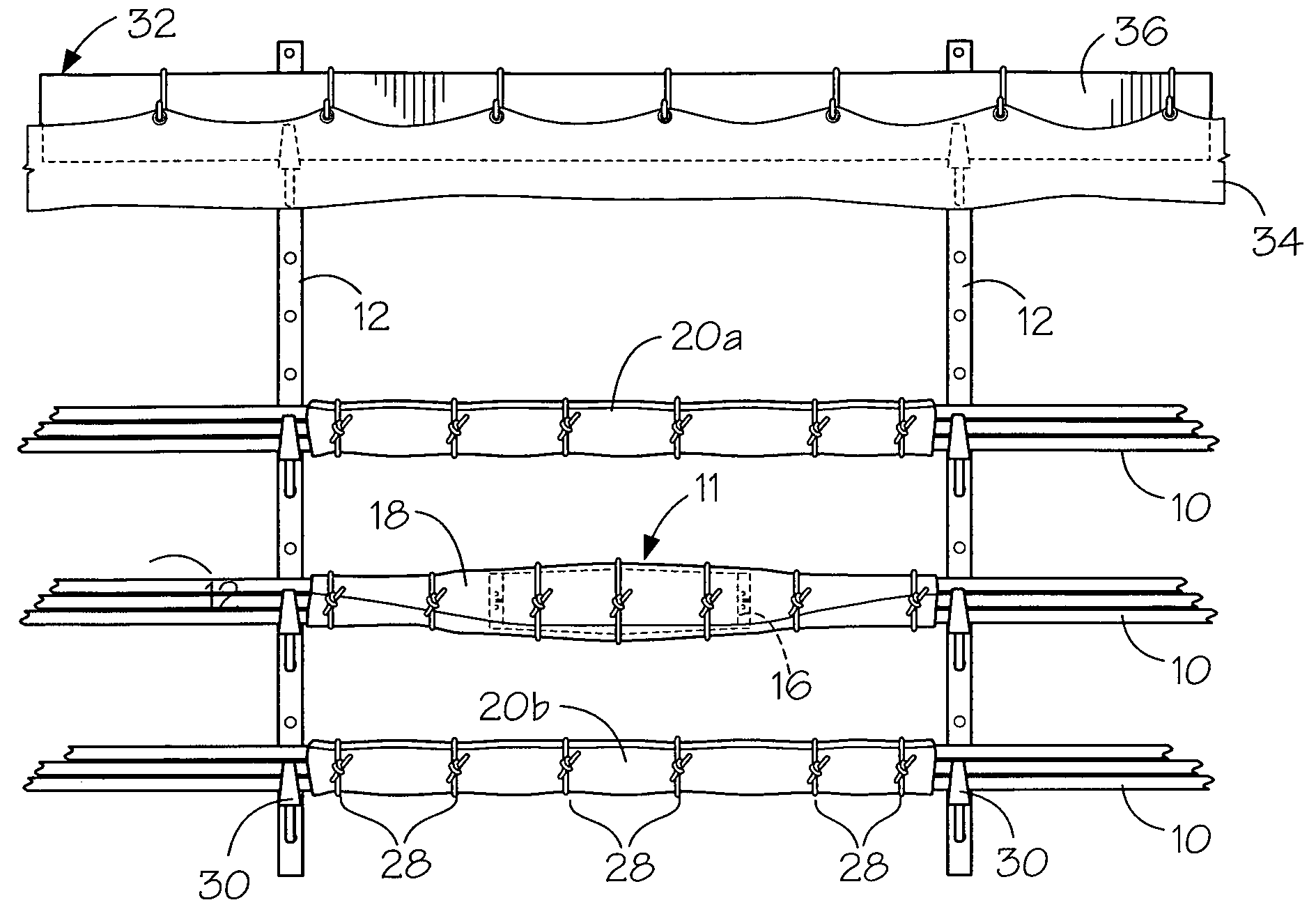
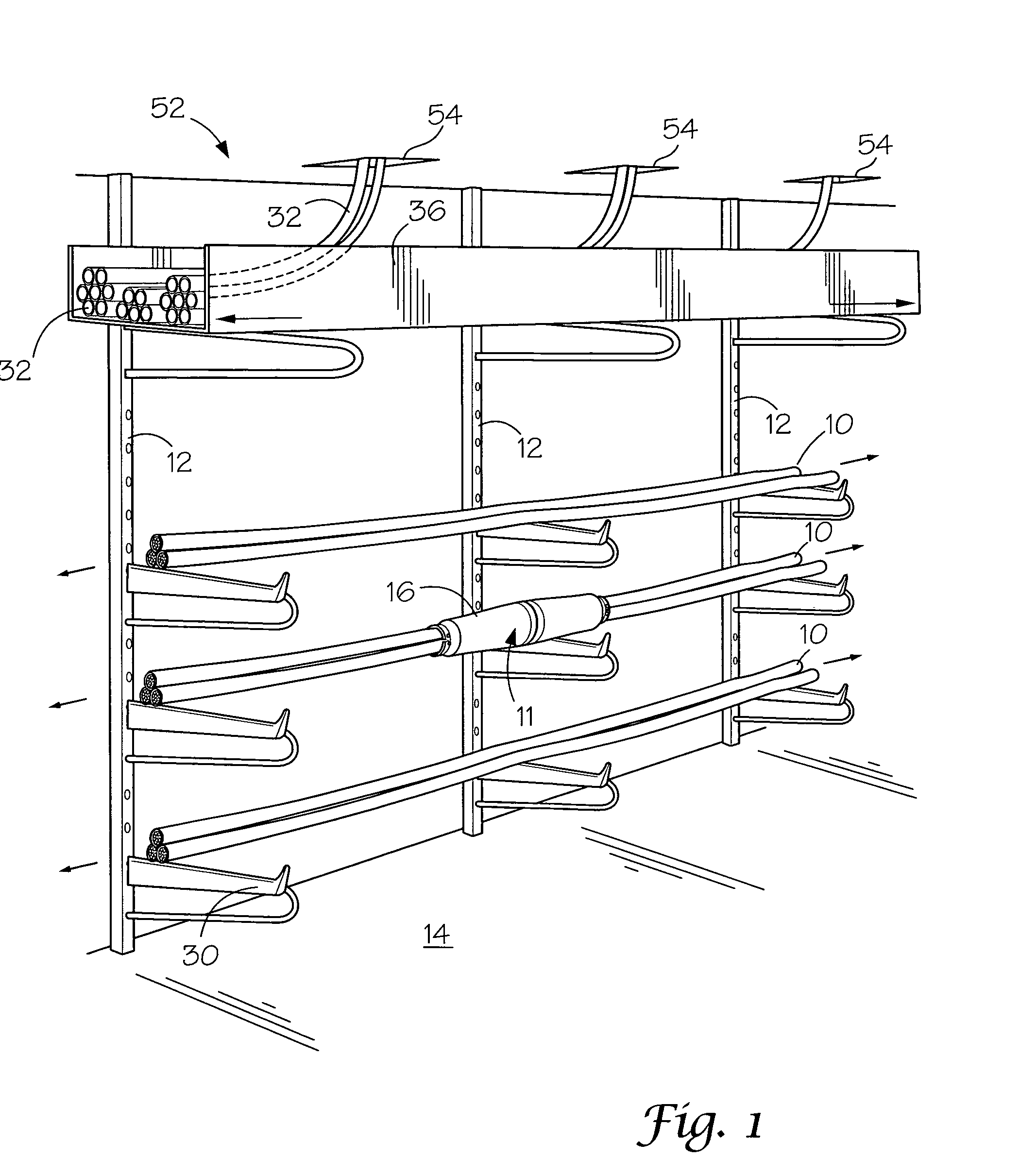
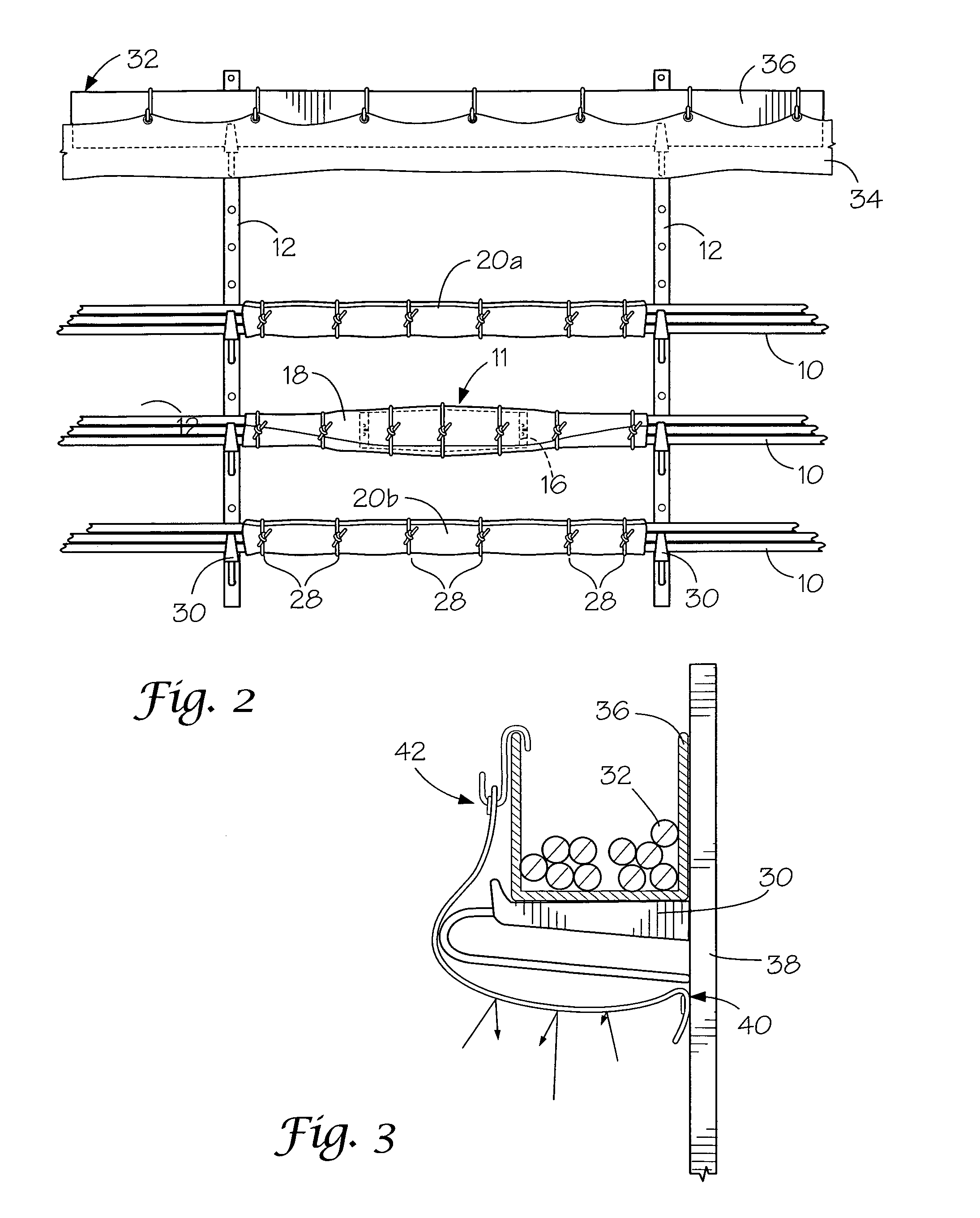
[0044]With reference to the drawings, the invention will now be described in more detail. A comprehensive approach to passive fire protection for high-risk facilities such as electrical power plants and electrical sub-stations is accomplished according to the present invention by providing a system and method that includes the following: 1) fire penetration seals on all cable penetrations through floors; 2) power cable joint protection; 3) control cable protection; and, 4) hatchway cover protection. Together, these passive protection systems combine to provide effective fire containment and management. Each of these areas is described in further detail herein below.

[0045]As part of the comprehensive approach to passive fire protection, it is important to anticipate and protect against overheating and explosions of connections between power cables. When a cable joint, designated generally as 11 (FIG. 1) explodes, fire and molten metal from the cable fault typically knock out adjacent...


PUM

PropertyMeasurementUnit
depthaaaaaaaaaa
lengthaaaaaaaaaa
depthaaaaaaaaaa

Abstract

A passive fire protection system for a power facility having a fire resistant wrap enclosing cable joints and adjacent power cables; a fire resistant sheet carried between the power cables and the control cables defining a fire barrier to resist fire from the power cables damaging the control cables; a fire resistant wrap on a cable drop section of the control cables so that the cable drop section is protected from burning power cables; a radiant heat shield carried on a bottom side of a hatchway cover leading from the room containing the power cables to deflect heat from passing through the hatchway cover into a floor above the basement; and, a fire penetration seal in each cable penetration opening to resist fire and heat from passing upward into adjacent floors of the power facility.

Description

CROSS REFERENCE TO RELATED APPLICATION[0001]This application claims priority from U.S. Provisional Application filed Nov. 19, 2007 under Application No. 61 / 003,680.BACKGROUND OF THE INVENTION[0002]1) Field of the Invention[0003]The present invention relates to fire protection for high-risk facilities such as electrical power plants and electrical sub-stations, and more particularly, to a comprehensive passive fire protection system to prevent fire damage from burning power cables from spreading between adjacent power cables, control cables, equipment and rooms of utility facilities.[0004]2) Description of Related Art[0005]Fire protection for power facilities is a critical component of their construction given the tendency for fires to occur at such facilities. A fire at an electrical sub-station can cause substantial damage to equipment, cause outage time to a service area, and cost millions of dollars to repair if proper fire prevention techniques are not used. Unfortunately, the c...

Claims


Application Information

Patent Timeline
Patent Type & Authority Patents(United States)
IPC IPC(8): H02G3/04
CPCA62C3/16H02G3/22H02G3/0412Y10T29/53209F16L5/04H02G3/0456H02G3/263H02G3/30
Inventor FORD, JIMSLMMA, LANCE
Owner LUSE THERMAL TECH
Why Eureka
Try Eureka