Dual mode stepper motor

a stepper motor and stepper motor technology, applied in the direction of electric controllers, dynamo-electric converter control, electric program control, etc., can solve the problems of limited useable speed range and challenge of vibration, and achieve the effect of reducing vibration and noise of such motors

Inactive Publication Date: 2009-07-14
XEROX CORP
View PDF11 Cites 11 Cited by
  • Summary
  • Abstract
  • Description
  • Claims
  • Application Information

AI Technical Summary

Benefits of technology

[0001]Embodiments herein generally relate to structures and methods that control the speed of electric motors such as stepper motors, and more particularly to an improved motor and method that utilizes two modes to reduce vibrations and noise of such motors.
[0009]However, the controller performs the open-loop mode control to supply, from the controller to the electric motor, sinusoidal voltage waveforms matching desired sinusoidal current waveforms corresponding to the desired rotational speed. The current feedback loop is adapted to provide over-current protection during the open-loop mode control.

Problems solved by technology

However, even with micro-stepping techniques, vibration continues to be a challenge with popular drive circuitry, as does limitations on the useable range of speed.
However the mechanical position of a torque loaded motor will stray from this by a positional error called the load angle, as shown in FIG. 2.

Method used


Image

  • Dual mode stepper motor
  • Dual mode stepper motor
  • Dual mode stepper motor

Examples


Embodiment Construction

[0017]While the present method and structure will be described in connection with embodiments thereof, it will be understood that this disclosure is not limited to the disclosed embodiments. To the contrary, this disclosure is intended to cover all alternatives, modifications, and equivalents as may be included within the spirit and scope, as defined by the appended claims.

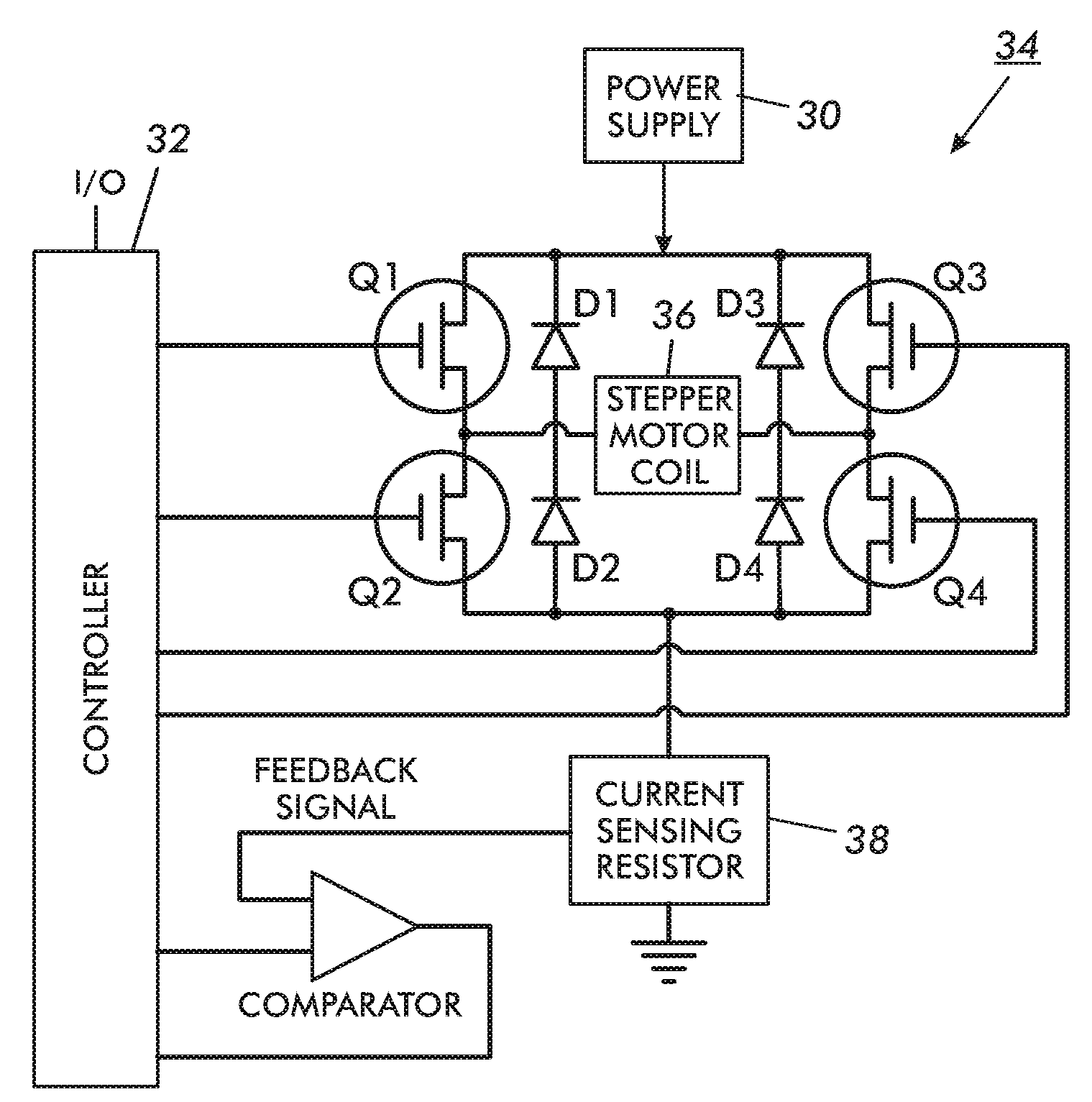
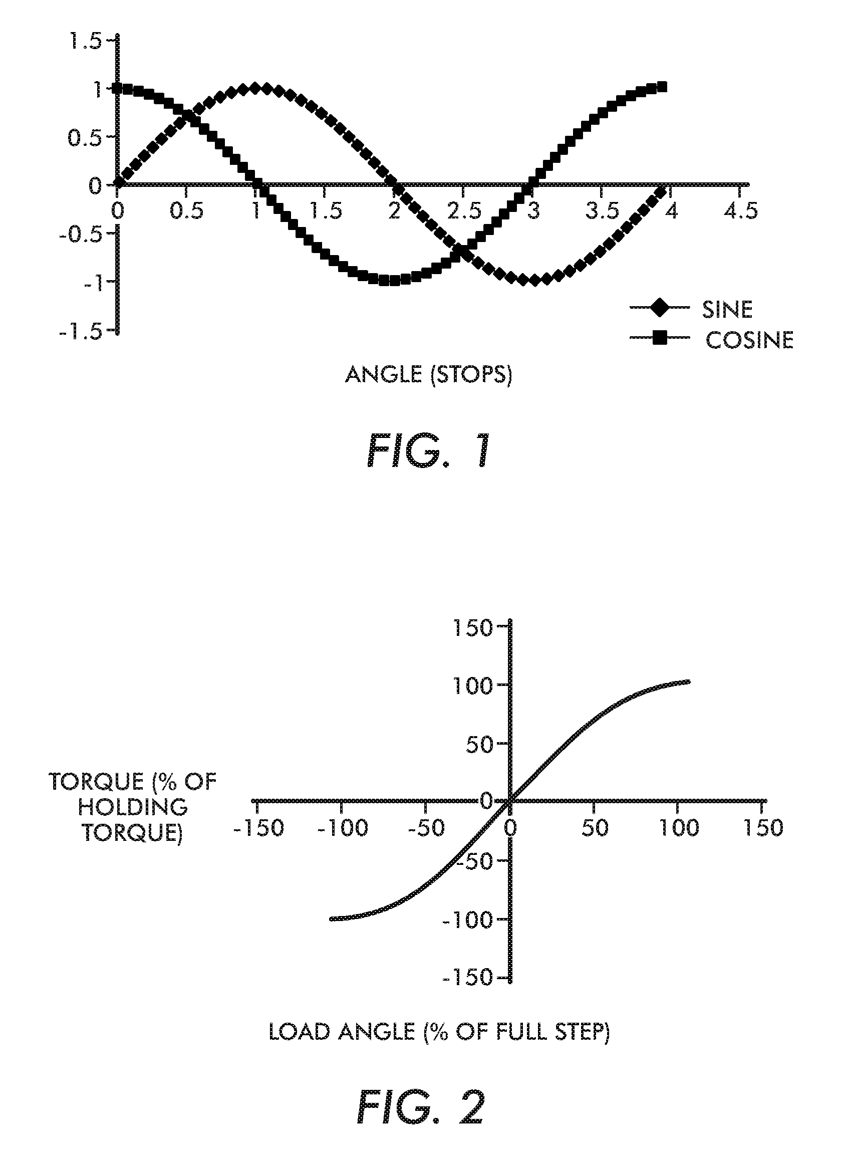
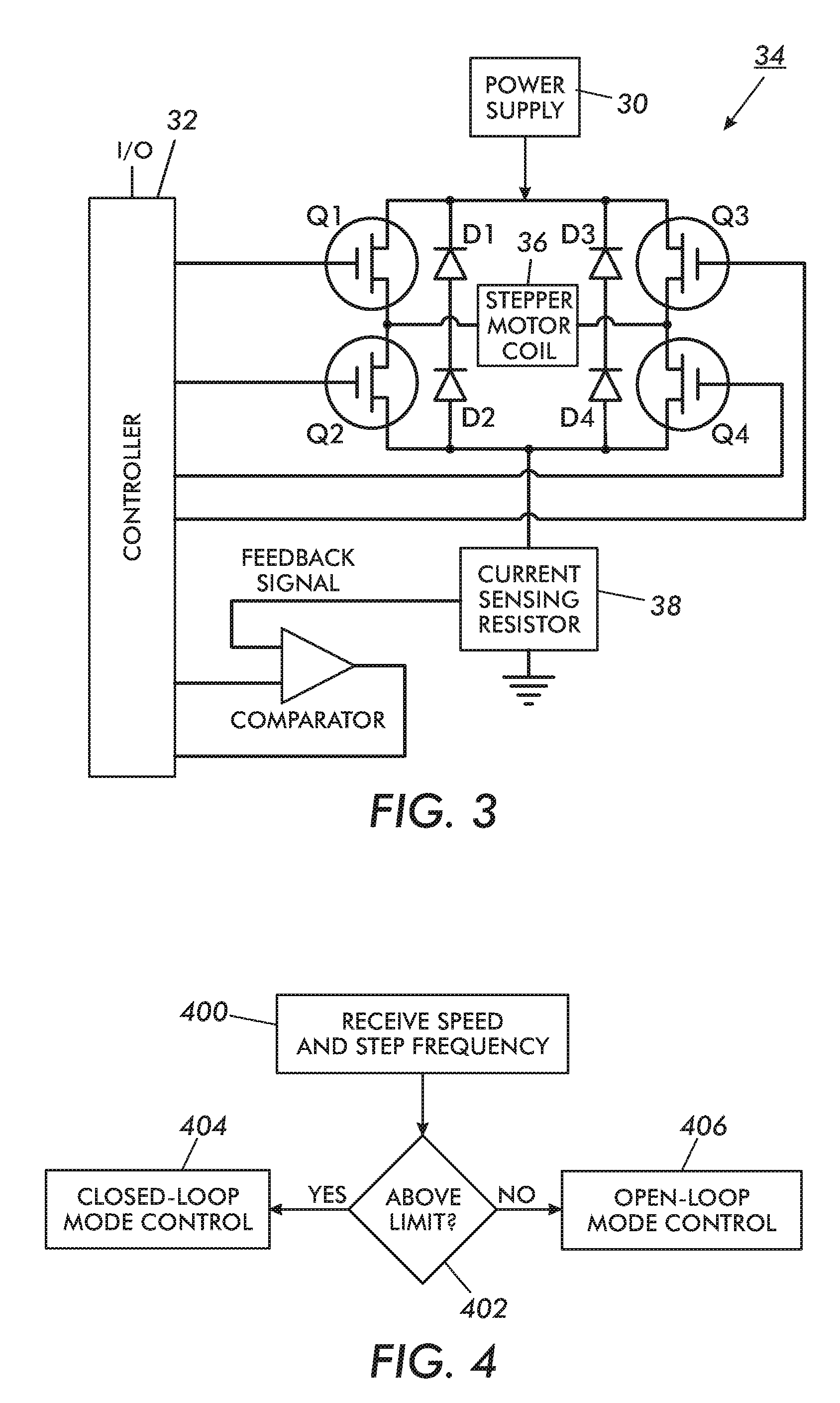
[0018]As mentioned above, the load angle shown in FIG. 2 can cause harmonic motion. Since any imperfection causing noise at the resonant frequency can build up this oscillation amplitude, a damping mechanism is needed. Damping occurs when velocity of the load angle causes a force that tends to restore that velocity to zero. Damping may be accomplished mechanically by means of tuned resonant dampers, or electromechanically which is the focus of this disclosure. The feedback of load angle velocity to acceleration force may be accomplished through a simple local loop, or an extravagant remote loop. This disclosure fo...


PUM


Abstract

A method and structure receives a desired rotational speed and / or step frequency for an electric motor. If the desired rotational speed is above a predetermined limit, the method performs closed-loop mode control of coil current of the electric motor by varying the average voltage supplied to the electric stepper motor according to observed feedback current from the current feedback loop connected to the electric stepper motor. To the contrary, if the desired rotational speed is not above the predetermined limit, the method performs open-loop mode control of coil current of the electric stepper motor by setting the average voltage supplied to the electric stepper motor according to values computed from the step frequency, irrespective of the observed feedback current from the current feedback loop.

Description

BACKGROUND AND SUMMARY[0001]Embodiments herein generally relate to structures and methods that control the speed of electric motors such as stepper motors, and more particularly to an improved motor and method that utilizes two modes to reduce vibrations and noise of such motors.[0002]Where perfect speed control is required, hybrid stepper motors are often chosen for their precision, in order to minimize vibration. However, even with micro-stepping techniques, vibration continues to be a challenge with popular drive circuitry, as does limitations on the useable range of speed. This disclosure explains how standard drive circuit topology can be used along with enhanced control logic to accomplish very low vibration operation over an unprecedented range of speed.[0003]When a stepper motor is used to produce continuous motion, it periodically updates the electrical signal supplied to the coils. To keep the torque constant and the angular increment regular, the coils of a 2-phase bipola...

Claims


Application Information

Patent Timeline
Patent Type & Authority Patents(United States)
IPC IPC(8): G05B19/40H02P6/20
CPCH02P8/12H02P8/34H02P8/14
Inventor THOMSON, BARRY
Owner XEROX CORP
Why Eureka
Try Eureka